
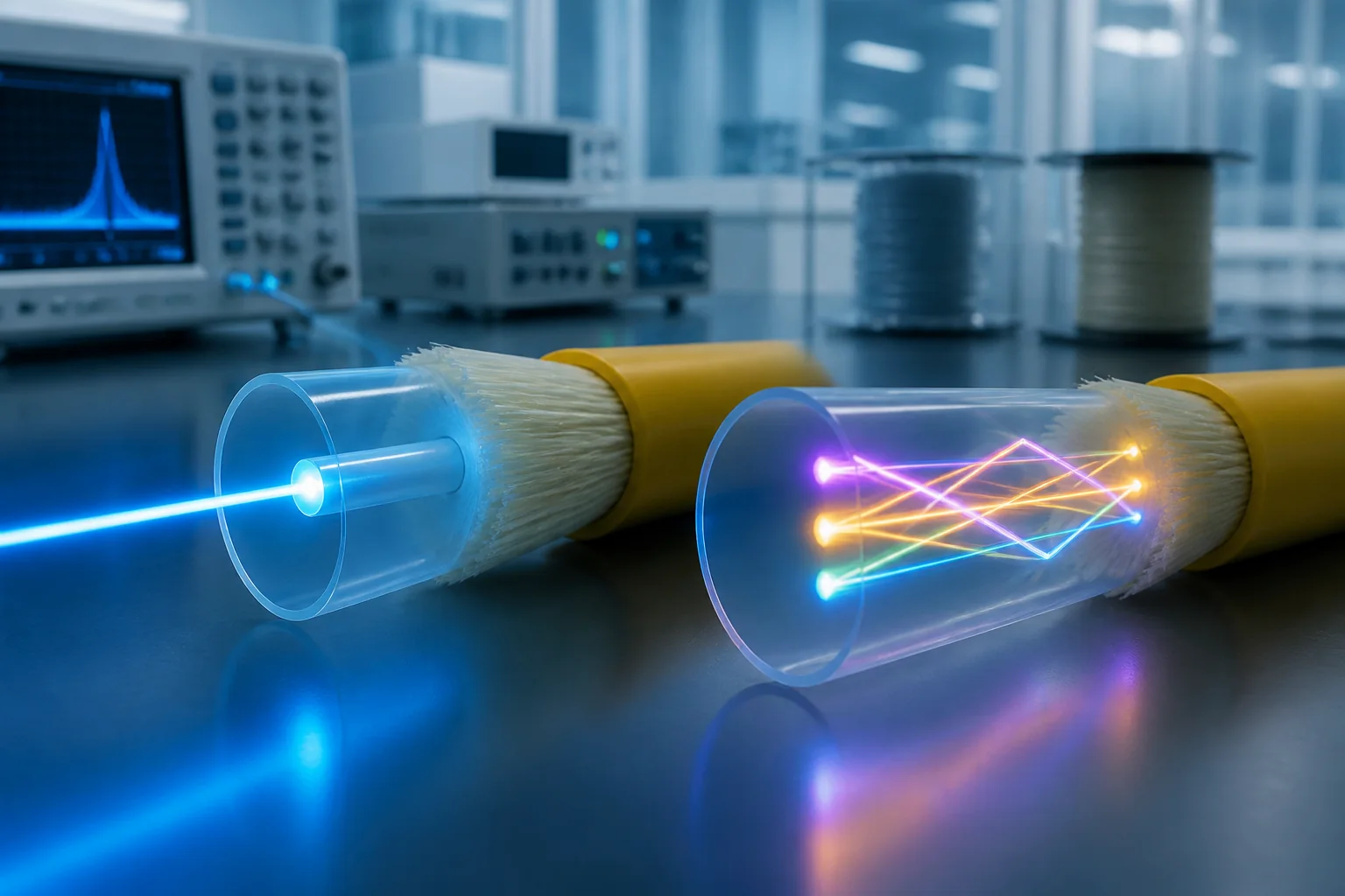
Choose the optical fiber before choosing the cable
Optical fiber is the glass transmission medium inside a cable, but the fiber designation and the cable construction answer different questions. The fiber determines optical characteristics such as attenuation, dispersion, mode field or core geometry and macrobending performance. The cable adds mechanical protection, strength members, water blocking, armor, sheath and installation ratings. A complete specification therefore names both an optical fiber type and a cable construction.
This page compares the principal optical fiber types used in telecom, FTTH, enterprise and data-center networks. It is a category and selection guide; project-specific values must be confirmed in the quotation, data sheet and acceptance report.
Optical fiber type comparison
| Fiber family | Typical decision context | Key items to verify |
|---|---|---|
| ITU-T G.652.D single-mode | Outside plant, metro, backbone and general telecom links | Attenuation at required wavelengths, dispersion, geometry and cabled performance |
| ITU-T G.657.A1 | Access, FTTH, compact routing and networks requiring G.652.D compatibility | Macrobending requirement, cable radius and installation practice |
| ITU-T G.657.A2 | Tighter access routing, drop cables, indoor pathways and dense closures | Smaller design bend radius, connection compatibility and route control |
| OM3 multimode | Short-reach premises and data-center links using compatible transceivers | Application reach, effective modal bandwidth, connector loss and polarity |
| OM4 multimode | Higher-bandwidth or longer multimode links than an equivalent OM3 design | Transceiver standard, channel length, connector count and installed loss |
| OM5 wideband multimode | Applications specifically designed to use its wavelength range | Actual transceiver ecosystem and system-level benefit instead of color alone |
G.652.D versus bend-insensitive G.657 fiber
G.652.D remains a common baseline for single-mode transport and outside-plant networks. The current ITU-T G.652 recommendation covers geometrical, mechanical and transmission attributes of single-mode fiber and cable. It should not be reduced to one attenuation number: mode-field diameter, cutoff wavelength, chromatic dispersion, polarization-mode dispersion and macrobending behavior can also matter to a network design.
G.657 fiber is optimized for improved bending-loss performance. According to the current ITU-T G.657 recommendation, category A fibers remain compliant with G.652.D transmission and interconnection characteristics, while category B fibers serve more specialized short-reach, very-small-radius applications. G.657.A1 and A2 are therefore common candidates for access and dense routing, but bend-insensitive does not mean bend-proof. The finished cable’s minimum bend radius and the installation method still control the route.
For a focused engineering comparison, read G.652.D vs G.657.A1 vs G.657.A2. Buyers seeking a finished cable can continue to the single-mode fiber optic cable page.
Single-mode versus multimode is a system choice
Single-mode and multimode cannot be selected from fiber price alone. The decision depends on link length, required data rate, transceiver interface, installed connector count, pathway constraints, upgrade plan and the total cost of active and passive components. Multimode can be efficient for supported short-reach applications; single-mode is often preferred where distance, wavelength flexibility or long-term network architecture favors it.
For multimode, require the exact OM grade and verify the application reach against the selected Ethernet or Fibre Channel interface. For single-mode, identify the relevant ITU-T family and the wavelengths used by the system. A generic description such as “9/125 fiber” or “50/125 fiber” is not a complete purchasing specification.
Parameters to place in an optical fiber RFQ
| Specification field | What the buyer should state or request |
|---|---|
| Reference standard | Exact fiber designation and, where contractually required, edition or customer specification |
| Operating wavelengths | Wavelengths at which attenuation or other limits are required |
| Geometrical attributes | Mode-field or core diameter, cladding diameter and concentricity where relevant |
| Transmission attributes | Maximum attenuation, dispersion requirement and any application-specific bandwidth value |
| Bending requirement | Fiber category plus the finished cable’s installation and long-term bend radius |
| Mechanical evidence | Proof-test requirement, spool identification and traceable test documentation |
| Delivery form | Bare fiber spool, colored fiber, ribbon, buffered fiber or finished cable |
Illustrative link-loss calculation
A preliminary loss budget makes the fiber decision testable. For a 12 km single-mode route, assume 0.35 dB/km fiber attenuation at the design wavelength, four connector pairs at 0.30 dB each, eight splices at 0.10 dB each and a 3.0 dB engineering margin:
12 km × 0.35 dB/km + 4 × 0.30 dB + 8 × 0.10 dB + 3.0 dB = 9.2 dB.
This is an illustrative design budget, not a LIQIBA production measurement. Replace every assumption with the transceiver limits, route length, specified component losses and acceptance method for the real project. The calculation also shows why a fiber attenuation value cannot be evaluated independently from connectors, splices and margin.
Incoming inspection and acceptance evidence
For fiber supplied on spools, the receiving record should connect the product label, spool or lot identity, manufacturer data and ordered specification. For finished cable, confirm that the reported attenuation belongs to the delivered cable length and identifies the wavelength and test method. Where splice compatibility is critical, geometry and mode-field information may be more useful than a marketing description.
Our quality assurance guide explains how to structure limits, methods and records. The bidirectional OTDR case shows how event data and direction can affect an installed-link interpretation.
Frequently asked questions
Is G.657.A2 always better than G.652.D?
No. G.657.A2 offers stronger macrobending performance, but the correct choice still depends on the network owner’s specification, route, cable design, splicing practice and commercial requirements.
Can OM3 and OM4 be mixed in one channel?
Physical connection may be possible, but channel performance must be evaluated against the lowest-performing component and the application’s reach and loss limits. A consistent, documented fiber grade is easier to qualify.
Does fiber type define the cable bend radius?
No. Fiber bend performance contributes to the design, while the finished cable construction determines the cable’s specified installation and operating bend radius.
What information is needed for a quotation?
Send the fiber designation, delivery form or cable application, wavelength limits, quantity, spool or cable length, required reports, destination and schedule. Use the contact page to request a quotation.
