
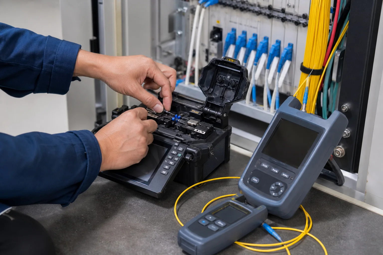
Build the tool kit around the work sequence
Fiber optic tools should follow the job from cable access through final documentation. Buying a generic kit without the cable, connector and test method often creates gaps: the stripper may not match the coating, the cleaver may not support the splice workflow, the inspection probe may lack the correct tip, or the test set may answer a different acceptance question.
A practical sequence is survey and safety, cable preparation, fiber preparation, termination or splicing, inspection and cleaning, continuity/polarity, insertion-loss testing, OTDR troubleshooting and report handover.
Fiber optic tool categories
| Work stage | Typical tools | Compatibility check |
|---|---|---|
| Cable access | Jacket slitter, ring tool, armor tool, tube cutter and strength-member cutter | Cable diameter, sheath, armor, tube depth and safe blade control |
| Fiber preparation | Coating stripper, lint-free wipes, approved solvent and precision cleaver | Coating size, fiber type, cleave length and splicer holder |
| Splicing | Fusion splicer, electrodes, holders, heater and protection sleeves | Fiber program, sleeve size, power, calibration and environment |
| Inspection/cleaning | Video probe, adapter tips, one-click cleaners, swabs and wipes | LC/SC/MPO/APC interface and IEC inspection workflow |
| Verification | Visual fault locator, fiber identifier and polarity/continuity tools | Wavelength, connector, safe power and live-fiber procedure |
| Loss testing | Light source and power meter or OLTS with reference cords | Wavelength, fiber mode, reference method and connector interface |
| Troubleshooting | OTDR, launch/receive fibers and event-analysis software | Wavelength, dynamic range, pulse width, dead zone and link length |
Cable and fiber preparation tools
Preparation is construction-specific. A jacket slitter must open the sheath without scoring buffer tubes or fibers. Armored cables can require controlled access tools and cut-resistant handling. Loose-tube work needs a cutter that avoids deforming the tube, while ribbon work requires compatible separation, cleaning and mass-fusion accessories.
For bare-fiber preparation, verify coating diameter and the splicer’s required strip and cleave dimensions. Keep cleaver blades clean and track blade position or cut count according to the manufacturer. A poor cleave can create splice loss, rework and unreliable protection even when the splicer displays an optimistic estimated result.
Fusion splicer selection
Core-alignment, cladding-alignment and mass-fusion systems serve different work profiles. Compare supported fiber types, holder system, average splice workflow, heater capacity, electrode life, battery endurance, environmental rating, service/calibration support and exportable records. A high-end splicer does not compensate for contaminated fiber, damaged cleaves or an incorrect program.
For production and project acceptance, distinguish the splicer’s estimated loss from an end-to-end measured link result. The estimate supports process control; OLTS and, where specified, bidirectional OTDR measurements provide different evidence about the installed link.
Inspect, clean and inspect again
Contaminated connector end faces are a major source of loss and reflection. A cleaning kit should include tools for both plugs and ports, plus inspection tips for every deployed connector. Protective caps are not evidence of cleanliness. Inspect a new or recapped connector before mating.
IEC 61300-3-35 defines quantitative end-face inspection methods. Fluke Networks summarizes the field process as inspect, clean and inspect again. Use the correct cleaner size for 1.25 mm, 2.5 mm or multifiber interfaces and follow the cleaning-product instructions.
OLTS, optical power meter and OTDR
| Instrument | Primary answer | Important setup |
|---|---|---|
| Optical power meter | What optical power reaches this point? | Correct wavelength/calibration and connector adapter |
| Light source + power meter / OLTS | What is the end-to-end insertion loss? | Reference method, test cords, direction and wavelengths |
| OTDR | Where are reflective or lossy events and how is loss distributed? | Launch/receive fibers, range, IOR, pulse width and averaging |
| Visual fault locator | Is there continuity or a visible fault in an accessible short link? | Laser safety, connector cleanliness and practical reach |
An OLTS is normally used for accurate end-to-end insertion loss, while an OTDR estimates event location, reflectance and distributed loss. Fluke Networks describes them as a complementary testing strategy. The FOA installation standard likewise calls for insertion-loss testing and identifies OTDR as useful for troubleshooting.
Read optical power meter vs OTDR and the bidirectional OTDR evidence case before specifying acceptance equipment.
Illustrative loss comparison
Assume a calculated link budget of 4.6 dB and a measured OLTS insertion loss of 5.3 dB. The link exceeds the design estimate by 0.7 dB. That result identifies a total-loss problem but not its location. An OTDR can then investigate whether the excess is associated with a connector, splice, bend or distributed section. The test direction and launch/receive setup influence event interpretation.
This example shows why one instrument does not replace the other. The contract should state which tests are required, at which wavelengths, in which direction and with what pass/fail limit.
Tool procurement checklist
- List every cable, coating, connector and adapter interface in the project.
- Define the number of crews, expected daily volume and field environment.
- Specify calibration, consumables, spare electrodes/blades and local service.
- Confirm report export, project naming, cable-ID workflow and software compatibility.
- Include launch/receive fibers, reference cords, cleaning tools and inspection tips.
- Define protective cases, battery/charger requirements and destination plug type.
Do not compare instrument price without accessories and service. An OTDR without suitable launch cords or an inspection camera without the deployed adapter tips is not a complete kit.
Safety and maintenance
Never look into a fiber or connector. Verify live-fiber status with approved procedures and equipment. Control glass shards in a dedicated container, use eye protection where required and follow solvent and battery instructions. Maintain calibration records for measurement equipment and verify reference cords before blaming the installed cable.
For a full work sequence, read the fiber optic installation and testing guide. If you need a kit matched to a particular cable and connector system, send the scope and tool list to sales.
Frequently asked questions
Do I need both an OLTS and an OTDR?
Often yes. The OLTS measures total insertion loss; the OTDR helps locate and characterize events. Project specifications determine whether both are required.
Can a visual fault locator test link loss?
No. It is useful for continuity and visible fault tracing in suitable conditions, but it does not replace calibrated insertion-loss measurement.
Why are launch and receive fibers used with an OTDR?
They allow the instrument to evaluate the first and last connections outside its near-end and far-end limitations and provide a more complete event view.
What information is needed for a tool quotation?
Provide cable/fiber types, connector interfaces, work stages, crew count, test standards, wavelengths, report format, destination and service expectations.
