
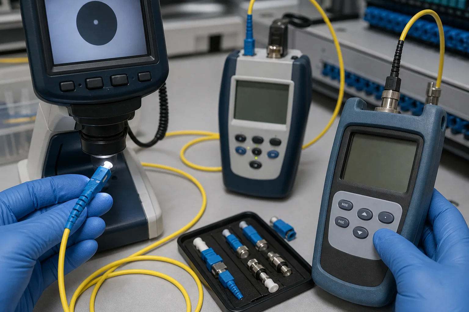
A patch cord is a complete optical assembly
Fiber optic patch cords connect equipment, panels, cassettes and distribution frames. A connector name is only the first field in the specification. Reliable ordering also defines the interface on both ends, polish, fiber mode, simplex/duplex or multifiber arrangement, polarity, jacket, diameter, length tolerance, labeling and optical acceptance limits.
The assembly must match the network as a system. An LC/UPC duplex cord for a multimode switch link, an SC/APC simplex jumper for PON equipment and an MPO trunk for parallel optics have different interface, polarity, cleaning and test requirements.
Patch cord configuration guide
| Field | Typical options | Why it matters |
|---|---|---|
| Connector | LC, SC, FC, ST, MPO/MTP or hybrid | Must match the equipment or adapter interface and density |
| Polish | UPC or APC | Affects return performance and physical mating compatibility |
| Fiber mode | OS2 single-mode; OM3/OM4/OM5 multimode as required | Must match the link and transceiver application |
| Fiber count | Simplex, duplex or multifiber | Defines path count, polarity and connector format |
| Cable body | Round, zipcord, uniboot, armored or breakout | Changes routing, handling, density and protection |
| Jacket | Material and performance class required by pathway | Supports environmental and building requirements |
| Acceptance | Insertion loss, return loss, visual inspection and mapping | Turns “low loss” into measurable criteria |
LC, SC, FC and MPO/MTP interfaces
LC is widely used where port density matters. SC uses a larger push-pull body and remains common in telecom, enterprise and PON networks. FC uses a threaded coupling in suitable applications, while ST is found in some installed or industrial systems. Hybrid cords place different interfaces at each end and must be labeled clearly to avoid reversal during installation.
MPO/MTP assemblies require additional fields: populated fiber count, male or female connector, guide pins, key orientation, polarity method and channel map. Review the dedicated MPO/MTP patch cord sourcing page when the link uses parallel or multifiber connectivity.
UPC and APC must not be intermated
UPC and APC describe different end-face geometries. APC connectors use an angled physical-contact interface and are commonly identified by green housings, while UPC single-mode interfaces are often blue. Color is a useful field cue but not sufficient evidence; verify the connector designation and equipment port. Intermating APC and UPC can create an air gap, high loss, poor reflectance and possible end-face damage.
Read UPC vs APC fiber connectors for a focused comparison. The selected adapter and test cords must use the same physical interface as the production assembly.
Insertion-loss planning example
For a channel containing two mated connector pairs, assume 0.30 dB per pair and 0.10 dB for fiber and other short-length allowance. The illustrative patching contribution is:
2 × 0.30 dB + 0.10 dB = 0.70 dB.
This is a planning example, not a LIQIBA measured result or a universal product limit. A purchase order should state the maximum insertion loss per assembly or mated pair, the test wavelength, reference method and report format. “Low loss” without a numeric limit is not an acceptance criterion.
Polarity and duplex orientation
A duplex channel must connect transmitter to receiver. Duplex clips, A-to-B orientation, cassette mapping and equipment port labeling all influence the path. Uniboot cords may support field polarity changes, but the permitted method should be documented. For MPO systems, evaluate polarity from transceiver through trunks, cassettes and duplex jumpers instead of approving each part in isolation.
Where pre-terminated assemblies are supplied, request a channel map or fiber-position report in addition to an overall pass statement. This prevents a mechanically correct but logically reversed installation.
Inspection, cleaning and optical testing
Connector cleanliness directly affects loss and reflectance. The current IEC 61300-3-35 edition addresses visual inspection of connector end faces. Fluke Networks’ guidance recommends an inspect, clean and inspect-again workflow before mating.
For incoming inspection, sample cords across lots and lengths. Verify labels and configuration first, then inspect both end faces with the correct adapter tip. Test insertion loss using the specified reference method and compatible launch cords. Return-loss testing may be required for single-mode, APC or reflection-sensitive applications. Keep protective caps clean and do not treat a cap as proof that the end face is clean.
What to include in a patch-cord RFQ
- Connector type and polish on end A and end B.
- Single-mode or exact multimode grade, fiber count and polarity.
- Cable construction, diameter, jacket requirement, color and length tolerance.
- Boot style, pull tab, clip, breakout, pulling eye or armor where required.
- Insertion-loss and return-loss limits, wavelengths, inspection criterion and report fields.
- Label format, packaging, quantity, destination and requested delivery schedule.
For non-standard interfaces, lengths, breakouts or labels, use the custom fiber optic cable assembly page. You can also compare fiber optic adapters used to mate the finished cords.
Frequently asked questions
Can an APC patch cord plug into a UPC adapter?
The adapter sleeve may accept the connector body, but the complete mated interface must be APC-to-APC or UPC-to-UPC. Never use an adapter to justify intermating different polish geometries.
Does patch-cord length affect loss?
Fiber attenuation over a short jumper is usually small compared with connector loss, but length still affects routing, slack, bend control and documentation. Very long assemblies require the fiber contribution in the budget.
Should every patch cord have a test report?
The required scope depends on risk and contract. Define whether the order needs 100% insertion-loss testing, return loss, end-face images, sampling or lot summaries before pricing.
How do I request a quotation?
Send the complete end-A/end-B schedule, fiber, polarity, construction, lengths, limits, quantity and destination through the RFQ contact page.
