
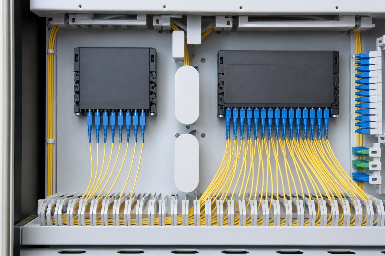
What a PLC fiber splitter does
A planar lightwave circuit (PLC) splitter distributes optical power from one or two inputs to multiple outputs without powered electronics. It is a fundamental passive component in FTTH and other point-to-multipoint optical distribution networks. The split ratio has the largest effect on loss, but connector loss, excess loss, uniformity, wavelength range, package and environmental reliability also matter.
A correct selection begins with the network architecture and optical budget, then defines the physical package. Buying only by “1×16” or “1×32” can produce the wrong connector, fiber length, module size or acceptance limit.
1×N and 2×N splitter configurations
| Configuration | Network use | Items to define |
|---|---|---|
| 1×2 / 1×4 | Low-ratio branching or first stage in a cascade | Architecture, excess loss and downstream stages |
| 1×8 / 1×16 | Moderate subscriber count or distributed splitting | Port count, enclosure capacity and budget margin |
| 1×32 / 1×64 | Higher split ratio from one feeder | OLT class, reach, connector/splice count and reserve |
| 2×N | Designs requiring two input paths or protection strategy | Architecture, isolation/directivity and operational method |
| Cascaded splitters | Centralized plus distribution-stage branching | Total ratio, stage loss, inventory and fault isolation |
Theoretical splitting loss
For equal outputs, ideal power-division loss is 10 × log10(N), where N is the number of output ports. It is a physical starting point, not the maximum insertion-loss specification of a manufactured splitter.
| Equal split | Ideal division loss | What must still be added |
|---|---|---|
| 1×2 | 3.01 dB | Excess loss, connectors/splices and system margin |
| 1×4 | 6.02 dB | Excess loss, connectors/splices and system margin |
| 1×8 | 9.03 dB | Excess loss, connectors/splices and system margin |
| 1×16 | 12.04 dB | Excess loss, connectors/splices and system margin |
| 1×32 | 15.05 dB | Excess loss, connectors/splices and system margin |
| 1×64 | 18.06 dB | Excess loss, connectors/splices and system margin |
For a public product benchmark, Corning’s PLC optical splitter specification publishes insertion loss, uniformity, polarization-dependent loss, return loss and directivity by ratio. Those values describe that referenced product family; request the contractual LIQIBA limits in the quotation.
Illustrative PON loss-budget example
Assume a 1×32 splitter with a specified maximum insertion loss of 17.1 dB, 10 km of fiber at 0.35 dB/km, four connector pairs at 0.30 dB, six splices at 0.10 dB and a 3.0 dB engineering margin:
17.1 + (10 × 0.35) + (4 × 0.30) + (6 × 0.10) + 3.0 = 25.4 dB.
This is an illustrative planning calculation, not a measured project result. Compare the completed budget with the applicable OLT/ONU optical class and network-owner limits. ITU-T G.984.2 defines physical-layer requirements and optical budget classes for GPON systems.
For more worked examples, see the FTTH 1×32 splitter loss budget and 1×8 vs 1×16 PLC splitter comparison.
Package styles
| Package | Typical integration | Procurement details |
|---|---|---|
| Bare fiber | Protected assembly integrated into another module | Fiber type, coating/buffer, length and handling controls |
| Mini steel tube | Compact module for closures, boxes and trays | Tube size, pigtail length, connectorization and bend management |
| ABS box | Protected module with pigtails | Box dimensions, port labels, lead length and mounting |
| LGX/cassette | Modular rack or cabinet deployment | Chassis compatibility, front interface and port numbering |
| Rack-mount or tray | Centralized high-port-count distribution | Rack unit, adapter panel, routing, access and documentation |
Physical design influences installation loss and serviceability. Pigtail length must reach the splice or adapter field without tight bends. Port labels must match the ODN design, and connector polish must match the equipment and distribution interfaces.
Optical parameters to specify
- Configuration, split ratio and operating wavelength range.
- Maximum insertion loss for every output and maximum uniformity across outputs.
- Polarization-dependent loss, return loss and directivity requirements.
- Connector type/polish, fiber type, pigtail length and package dimensions.
- Operating/storage temperature and required reliability or environmental tests.
- Port-level test report, lot identity, label format and packaging.
Uniformity matters because the highest-loss output can define the network’s worst-case reach. Review output-by-output data rather than relying only on an average value. Return loss and directivity become important where reflections or upstream/downstream isolation affect system performance.
Centralized versus distributed splitting
Centralized splitting places a higher-ratio splitter at a main distribution location, simplifying inventory and optical-path visibility. Distributed splitting cascades lower-ratio splitters closer to users, which may suit geography or incremental growth but adds stages and documentation complexity. Neither is universally superior. Compare feeder/distribution fiber utilization, enclosure space, restoration, take rate, test access and total worst-case loss.
Quality and sourcing
The order should define whether insertion loss is tested at all relevant wavelengths and on every output port. Report fields should identify input/output mapping, serial or lot reference, limit and measured result. Package inspection should verify pigtail damage, connector cleanliness, labels and module dimensions before deployment.
Commercial requirements—including custom ratios, packages, connector combinations and reports—belong on the PLC splitter manufacturer page. Review quality assurance before issuing the RFQ.
Frequently asked questions
Why is a 1×32 splitter loss higher than 15.05 dB?
15.05 dB is ideal equal power division. A real device adds excess loss and may include connectors, so the contractual maximum insertion loss is higher.
Can two splitters be cascaded?
Yes, when the ODN is designed for cascading. Add the worst-case loss of every stage, connections, fiber and margin, and document the total split ratio.
Is an unconnectorized splitter lower loss?
Removing connector interfaces can reduce connection contributions, but it requires controlled splicing and may change serviceability. Compare the complete installed path.
What should be sent for a quote?
Provide ratio, topology, package, connector/polish, pigtail lengths, limits, report scope, quantity and destination through the contact page.
