
If you’re choosing between an optical power meter (OPM) and an optical time-domain reflectometer (OTDR), the short answer is: you need both—but for different jobs. An OPM measures the absolute optical power at a single point, while an OTDR maps loss and reflectance along the entire fiber length. For most field troubleshooting, start with an OPM for quick pass/fail checks; use an OTDR when you need to locate faults, characterize splices, or certify a new link.
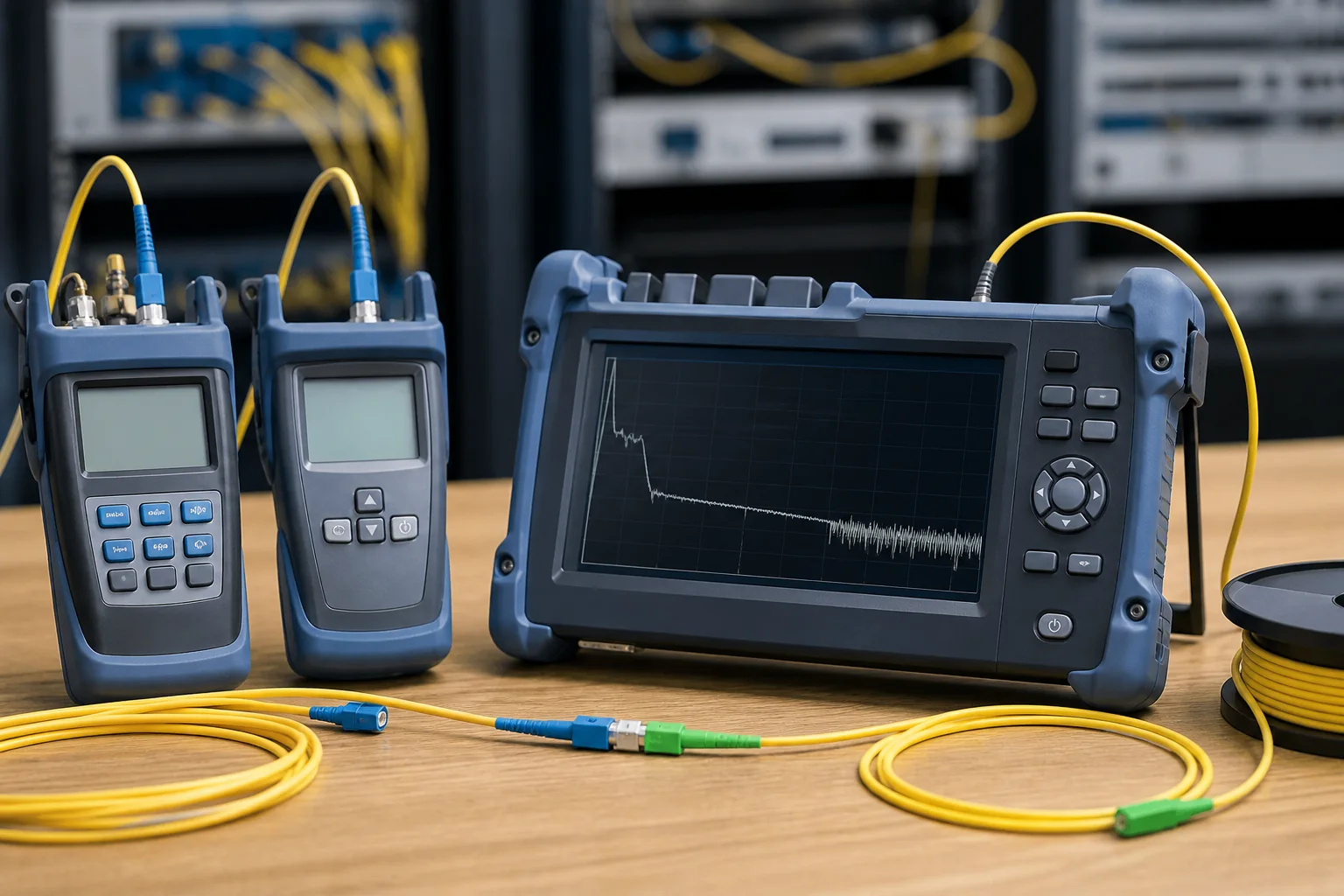
What Is an Optical Power Meter?
An optical power meter is a simple, handheld device that measures the average optical power of a light signal at a specific connector or splice point. It typically works with a light source (e.g., a laser or LED) at a known wavelength—commonly 850 nm, 1300 nm, 1310 nm, or 1550 nm—and displays the result in dBm or microwatts.
Key Characteristics
- Single-point measurement: You connect the meter to one end of the fiber; it tells you the power arriving at that point.
- Wavelength-specific: You must select the correct wavelength to match your source and system.
- Calibration-dependent: Accuracy relies on proper calibration to a traceable standard.
OPMs are often paired with a light source to perform insertion loss tests: you launch a known power, measure the received power, and the difference is the link loss. This is the standard method for verifying that a fiber link meets its loss budget.
What Is an OTDR?
An optical time-domain reflectometer (OTDR) sends a series of high-power optical pulses into the fiber and analyzes the backscattered light as a function of time. Because light travels at a known speed in glass, the time delay corresponds to distance. The OTDR produces a trace that shows loss and reflectance events along the entire fiber length.
Key Characteristics
- Full-length view: One test gives you a graphical map of the fiber, including connectors, splices, bends, and breaks.
- Distance measurement: It calculates the distance to each event, which is essential for locating faults.
- Dead zone limitation: The OTDR cannot see events within a certain distance after a high-reflectance event (e.g., a connector), which is why you often need launch and receive fibers.
OTDRs are more expensive and require more training to interpret traces correctly. They are indispensable for commissioning new links, troubleshooting hard-to-find faults, and documenting fiber plant quality.
When Does the Question Matter?
The choice between an OPM and an OTDR becomes critical in several practical scenarios:
- Acceptance testing: For a new fiber link, the industry standard (e.g., TIA-568) typically requires both an insertion loss test (using an OPM and light source) and an OTDR test to document the link’s characteristics.
- Troubleshooting: If a link is down or has high bit-error rate, an OPM can quickly tell you if power is present and if it’s within budget. If the power is low, an OTDR helps you find where the loss is occurring.
- Maintenance and documentation: OTDR traces provide a permanent record of splice quality, connector reflectance, and fiber condition, which is invaluable for future troubleshooting.
In short, if you need a yes/no answer on whether a link meets its loss budget, use an OPM. If you need to know where a problem is, use an OTDR.
Core Technical Differences
Understanding the underlying physics helps you choose the right tool for each task.
Measurement Principle
An OPM measures the absolute power of a continuous or modulated light signal. It is a direct, calibrated measurement. An OTDR, on the other hand, measures backscattered light from a pulsed signal. It does not measure absolute power at a point; instead, it calculates loss between two points based on the change in backscatter level.
What You Get
- OPM: A single number (power in dBm) or, with a light source, a loss value in dB.
- OTDR: A trace showing loss (in dB) and reflectance (in dB) as a function of distance (in meters or kilometers).
Accuracy and Resolution
OPMs are highly accurate for measuring power—typical accuracy is ±0.2 dB or better, depending on calibration. They are the reference for absolute power. OTDRs are less accurate for absolute loss measurements because they rely on backscatter coefficients, which vary with fiber type and wavelength. However, OTDRs excel at relative measurements and event location.
Test Time and Complexity
An OPM test is fast and straightforward: connect, read, record. An OTDR test requires setting parameters (pulse width, wavelength, range), and interpreting a trace can be complex. OTDRs also require launch and receive cables to avoid dead zones, adding setup time.
Cost and Portability
OPMs are inexpensive and compact. OTDRs are significantly more expensive and often larger, though modern handheld OTDRs are quite portable. For many technicians, the practical approach is to carry an OPM for everyday checks and an OTDR for deeper troubleshooting.
In summary, the optical power meter vs OTDR decision hinges on your immediate goal: verifying power or locating faults. Both are essential in a professional fiber toolkit, but they serve different purposes. Choose the tool that answers your specific question with the least complexity and cost.
Optical Power Meter vs OTDR: Side-by-Side Comparison
When you place an optical power meter and an OTDR side by side, the differences go beyond the obvious price gap. The table below summarizes the key operational contrasts that affect your daily testing workflow.
| Parameter | Optical Power Meter | OTDR |
|---|---|---|
| Primary measurement | Absolute optical power at a single point (dBm or µW) | Loss and reflectance as a function of distance along the fiber |
| Typical use | End-to-end loss verification, transmitter power checks, receiver sensitivity tests | Fault location, splice loss assessment, link characterization, installation acceptance |
| Test setup | Requires a light source at the far end (if measuring loss) or a live transmitter | Standalone; injects its own laser pulses |
| Measurement output | Single power value (often with pass/fail against a reference) | Trace showing loss events, reflectance, and fiber length |
| Accuracy | High for absolute power; typical uncertainty ±0.2 to ±0.5 dB (calibrated) | Distance accuracy typically ±0.5 m to ±1 m; loss accuracy depends on settings and event spacing |
| Test time | Seconds per measurement | Seconds to minutes depending on range and averaging |
| Skill required | Basic; minimal training | Moderate; requires trace interpretation |
| Cost (typical range) | $200 – $1,500 | $2,000 – $15,000+ |
Note: Accuracy and cost figures are typical engineering values, not normative requirements. Always refer to manufacturer specifications and relevant standards (e.g., IEC 61280-4-2 for installed fiber loss testing).
Decision Criteria: Which Test Do You Actually Need?
Choosing between an optical power meter and an OTDR is not about which is “better”—it is about matching the tool to the question you need answered. Use these criteria to guide your choice.
When an Optical Power Meter Is the Right Choice
- End-to-end loss verification: You need to confirm that the total link loss meets the design budget. A power meter paired with a light source (often called an OLTS) gives you a direct pass/fail result.
- Live network testing: You are checking transmitter output power, receiver input power, or measuring insertion loss on a dark fiber using a known source.
- Routine maintenance: You want a quick, repeatable check of a specific link without the complexity of trace analysis.
- Budget constraints: If you only need pass/fail loss measurements, a power meter is far more affordable and easier to use.
When an OTDR Is the Right Choice
- Fault location: You need to find the exact distance to a break, bend, or bad splice. The OTDR’s distance capability is indispensable.
- Characterization of new installations: You must document splice loss, connector reflectance, and overall link quality. An OTDR trace provides a permanent record.
- Troubleshooting intermittent issues: An OTDR can reveal subtle events like micro-bends that a power meter cannot pinpoint.
- Long-haul or high-fiber-count networks: When you have many fibers and need to identify specific problem segments, the OTDR’s spatial information saves time.
When You Might Need Both
In many professional settings, both tools are used together. For example, an OTDR is used to locate a suspected fault, then a power meter is used to verify the repair by measuring end-to-end loss. Some technicians carry a power meter for daily checks and reserve the OTDR for more complex diagnostics.
Worked Example: Choosing the Right Test for a 2 km Campus Link
Suppose you are responsible for a 2 km single-mode fiber link between two buildings on a campus. The link has been in service for several years, but users are reporting intermittent connectivity issues. You have both an optical power meter and an OTDR available. How do you decide which to use first?
Step 1: Define the Question
Your immediate question is: “Is the link loss within the acceptable range?” If yes, the problem may be elsewhere (e.g., electronics). If no, you need to locate the source of excessive loss.
Step 2: Start with the Optical Power Meter
Using a light source at one end and a power meter at the other, you measure the total link loss. You obtain a value of 3.8 dB at 1310 nm. The design budget for this link is 3.5 dB (typical for a 2 km link with two connector pairs and two splices). The measured loss exceeds the budget, indicating a problem. However, the power meter cannot tell you where the loss is occurring.
Step 3: Switch to the OTDR for Location
Now you connect the OTDR to one end of the fiber. The trace shows a significant loss event at 1.2 km, with a reflection spike that suggests a bad connector or a sharp bend. You also notice a splice at 0.8 km with slightly higher loss than expected. The OTDR gives you the exact distance to the problem, allowing you to dispatch a technician to the correct manhole or patch panel.
Step 4: Verify the Repair
After repairing the connector at 1.2 km, you re-measure the link loss with the power meter. The new reading is 2.9 dB, within budget. The combination of both tools gave you a complete solution: the power meter confirmed the problem, the OTDR located it, and the power meter verified the fix.
Selection Guidance: Building Your Testing Toolkit
If you are equipping a new team or updating your kit, consider the following practical advice.
For Basic Installation and Maintenance
If your work is limited to short links (e.g., within a building) and you only need pass/fail loss measurements, a power meter with a light source is sufficient. It is cost-effective, easy to train on, and meets most requirements for premises cabling (as per TIA-568 or ISO/IEC 11801, which specify loss limits but do not require OTDR testing for every link).
For Outside Plant and Long-Haul Networks
If you work on campus backbones, metro networks, or long-haul spans, an OTDR is essential. It provides the fault-locating capability that a power meter lacks. Many OTDRs now offer built-in power meter functions, so you can get both tools in one unit—though dedicated power meters often have better accuracy.
For Mixed Environments
Many technicians carry a handheld power meter for quick checks and an OTDR for deeper diagnostics. If budget allows, invest in a combined unit that includes both functions. This gives you flexibility without carrying two separate devices.
Ultimately, the choice between an optical power meter and an OTDR depends on the types of networks you support, the level of detail you need, and your budget. By understanding the strengths and limitations of each, you can select the right tool for each job—and know when to use both.
Installation and Testing Implications: What Each Tool Tells You
Choosing between an optical power meter and an OTDR is not just about cost or speed—it directly affects how you install, certify, and troubleshoot fiber links. The two tools answer fundamentally different questions during the lifecycle of a network.
Optical Power Meter: End-to-End Loss Verification
An optical power meter (OPM) measures the absolute optical power at a point in the link. When paired with a light source, it performs an end-to-end insertion loss test. This is the test that most closely matches the actual operating condition of the link: it tells you whether the total loss from transmitter to receiver is within the system’s power budget.
During installation, the OPM is used to verify that a newly spliced or connectorized link meets the loss budget specified by the design. It is also the standard tool for acceptance testing, because it measures the combined effect of all components—fiber, connectors, splices—just as the network equipment will see it.
However, an OPM cannot tell you where a loss occurs. If the total loss is too high, you know there is a problem, but you have no direct way to locate it. You might have to check each connector and splice manually, which is time-consuming and often impractical in long outside-plant runs.
OTDR: Event Location and Characterization
An OTDR sends short light pulses and analyzes the backscattered light to produce a trace of loss versus distance. This gives you a map of the link, showing events such as connectors, splices, bends, and breaks, along with their distance and loss. It is indispensable for troubleshooting and for locating faults.
But an OTDR does not directly measure the end-to-end loss as experienced by a transmitter. The OTDR’s measurement is based on backscatter, which is not the same as the forward loss. For example, a poor splice might show a small event loss on the OTDR, but its actual contribution to the total link loss could be different. Therefore, OTDR results are often used to identify where to investigate, but the final pass/fail decision is typically made with an OPM-based insertion loss test.
In practice, many installers use an OTDR during the construction phase to verify splices and to document the link, then use an OPM for the final acceptance test. This combination ensures both location information and accurate end-to-end loss.
Common Mistakes When Choosing or Using These Tools
Even experienced technicians can fall into traps that lead to inaccurate results or wasted time. Here are the most frequent pitfalls:
- Using an OTDR for final acceptance without an OPM: As noted, OTDR loss values are not directly equivalent to insertion loss. Many standards require a light source and power meter measurement for final acceptance, especially for single-mode links.
- Using an OPM to locate faults: If you only have an OPM, you might spend hours checking every connection point. An OTDR would pinpoint the fault in minutes.
- Ignoring the need for a light source: An OPM alone measures power, but to measure loss you need a stable light source. Some technicians mistakenly think an OPM can test a link without a source.
- Not cleaning connectors before testing: Dirty connectors are a leading cause of high loss and reflection. Always clean and inspect connectors before any test.
- Mismatched wavelengths: Ensure the OPM and light source are set to the same wavelength (e.g., 1310 nm or 1550 nm). Using the wrong wavelength gives meaningless results.
- Forgetting to set the OTDR’s index of refraction: The OTDR calculates distance based on the fiber’s refractive index. If this is not set correctly for the fiber type, distance measurements will be off.
Buyer Checklist: What to Look For
When you are ready to purchase a test tool, consider these features and specifications. Remember that some requirements are dictated by standards (e.g., for certification), while others are practical conveniences.
For an Optical Power Meter
- Wavelength support: Ensure it covers the wavelengths you use (typically 850/1300 nm for multimode, 1310/1550 nm for single-mode). Some meters also support 1490 nm or 1625 nm for PON or testing.
- Calibration: The meter should be calibrated to a traceable standard. Check the calibration certificate and recommended recalibration interval.
- Measurement range and accuracy: Typical accuracy is around ±0.2 dB, but this can vary. Choose a meter with a range that covers your expected power levels.
- Interchangeable adapters: You may need different connector types (SC, LC, FC). A meter with swappable adapters is more versatile.
- Data logging: For documentation, you might want a meter that can store and download results.
For an OTDR
- Dynamic range: This determines the maximum fiber length you can test. For short links (e.g., inside a building), a lower range is sufficient; for long-haul, you need higher range.
- Dead zone: The event dead zone affects your ability to see two close events (like a connector and a splice). Shorter dead zones are better for premises networks.
- Pulse width options: Different pulse widths allow you to trade off resolution and range. Look for a device with multiple pulse widths.
- Wavelength options: Multi-mode OTDRs typically use 850/1300 nm; single-mode use 1310/1550 nm. Some OTDRs offer multiple wavelengths in one unit.
- Automated analysis: Many OTDRs have auto-event mapping, which can save time, but always verify the results manually.
- Battery life and durability: Field devices should be rugged and have sufficient battery life for a full day of testing.
Practical Recommendation: Build a Balanced Toolkit
For most network professionals, the question is not which tool to buy, but which to use for a given task. If you are just starting out and have a limited budget, an optical power meter and light source is the most cost-effective choice for basic installation and maintenance. It will allow you to verify that a link is within budget, which is often all that is needed for short, simple runs.
However, if you work on outside plant, long-distance links, or any network where faults can occur at unknown locations, an OTDR is essential. It saves hours of troubleshooting and provides documentation that can be invaluable for maintenance.
In a perfect world, you would have both. Many field technicians carry a combined OPM and light source, and also have access to an OTDR for more complex jobs. If you can only buy one, consider your typical work: if you are mostly verifying new installations and doing basic troubleshooting, start with an OPM. If you are responsible for maintaining an existing network and need to locate faults quickly, invest in an OTDR.
Remember that the optical power meter vs OTDR decision is not a one-time choice; it is a matter of using the right tool for the right job. A balanced approach—using an OPM for end-to-end loss verification and an OTDR for fault location—will give you the most accurate and efficient testing process.
In conclusion, understand what each tool measures, avoid the common pitfalls, and choose based on your specific needs. With the right equipment and knowledge, you can ensure your fiber links are installed correctly and maintained effectively.
Frequently Asked Questions
What is the main difference between an optical power meter and an OTDR?
An optical power meter measures the absolute optical power level at a point, while an OTDR sends pulses and analyzes backscattered light to provide a trace of loss and reflectance along the fiber length.
When should I use an optical power meter instead of an OTDR?
Use an optical power meter for end-to-end loss measurements and to verify that received power meets system requirements, especially for link acceptance testing or troubleshooting active connections.
What are the typical applications for an OTDR?
OTDRs are used for characterizing fiber spans, locating breaks or high-loss events, measuring splice and connector losses, and documenting the physical condition of the fiber over its entire length.
Can an OTDR replace an optical power meter for loss testing?
Not directly. OTDRs estimate loss from backscatter, which can be affected by fiber characteristics and reflectance, whereas a power meter with a light source measures true end-to-end insertion loss per industry standards.
What is a light source and why is it paired with an optical power meter?
A light source emits a stable optical signal at a specific wavelength. When used with an optical power meter, it forms a loss test set to measure the attenuation of a fiber link.
How do I choose between an optical power meter and an OTDR for my team?
Consider your tasks: for routine link loss testing, a power meter and light source are sufficient; for installation, maintenance, and fault location, an OTDR provides more detailed diagnostics. Many teams carry both.
Are there combined devices that offer both functions?
Yes, some handheld testers integrate both an OTDR and an optical power meter, allowing technicians to perform quick loss checks and detailed fiber analysis with a single unit.
Complete topic guide: Fiber Optic Installation and Testing: Complete Guide.







