
Answer: Yes, You Can Migrate from 40G to 100G Without Re-Cabling—But Only If Your Fiber Plant Meets Specific Criteria
Most 40G links deployed in data centers and enterprise networks use parallel optics over MPO connectors, typically with 12-fiber ribbons. The good news: the same 12-fiber MPO cabling can often support 100G—specifically 100GBASE-SR4; 100GBASE-SR10 instead requires 20 active fibers, commonly through MPO-24—depending on your fiber type and distance. However, migration is not a simple swap. You must verify your fiber plant’s polarity, insertion loss, and modal bandwidth. This guide explains exactly what to check and how to plan a seamless upgrade.
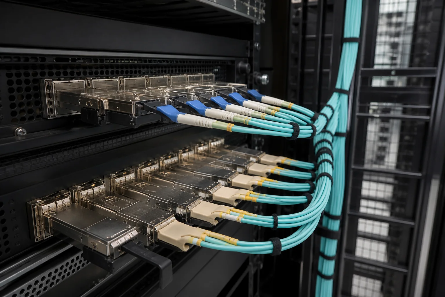
Core Definitions: 40G and 100G Optics and Cabling
To understand migration, you need to know the physical layer standards involved. These are defined by IEEE 802.3, and while the standards specify performance limits, actual deployment values vary.
40G Optics: 40GBASE-SR4
- 40GBASE-SR4: Uses 4 parallel multimode fiber lanes, each running at 10 Gbps. It requires an MPO-12 connector (using 8 fibers: 4 TX, 4 RX). Typical reach on OM3 is 100 meters, on OM4 150 meters (per IEEE).
- 40GBASE-SR4 uses four transmit and four receive fibers; verify the complete MPO channel mapping before reuse.
100G Optics: 100GBASE-SR10 and 100GBASE-SR4
- 100GBASE-SR10: Uses 10 lanes at 10 Gbps each, over MPO-24, reach of 100 m on OM3 or 150 m on OM4 for the cited SR10 module.
- 100GBASE-SR4: Uses 4 lanes at 25 Gbps each, over MPO-12 (8 fibers used). Reach is 70m on OM3, 100m on OM4 (per IEEE).
Key Cabling Components
- MPO connectors: Multi-fiber push-on, available in 8, 12, or 24 fibers. Polarity (A, B, C) matters for proper TX/RX alignment.
- Fiber types: OM3 (laser-optimized multimode, 2000 MHz·km effective modal bandwidth at 850nm) and OM4 (4700 MHz·km). OM5 is also an option but less common for 40/100G.
- Breakout cables: Fan-out from MPO to LC duplex or individual fibers.
When Does 40G to 100G Migration Matter?
This question is most relevant in three scenarios:
- Data center spine-leaf upgrades: You have 40G links between leaf and spine switches, and you need to increase bandwidth to 100G without pulling new cable.
- Enterprise campus backbones: Your building backbone runs 40G over multimode, and you want to consolidate to 100G.
- Storage area networks (SANs): If you’re moving from 40G Ethernet to 100G for storage traffic, the fiber plant may be reused.
In each case, the decision hinges on whether your existing cabling can support 100G optical transceivers. If your fiber is OM3 or OM4 and your link lengths are within the reach limits, you can often avoid re-cabling.
Core Technical Differences: Why 100G Is Not Just a Speed Increase
Migrating from 40G to 100G involves more than swapping transceivers. The physical layer requirements change significantly.
Lane Count and Data Rate per Lane
40G SR4 uses 4 lanes at 10 Gbps each; 100G SR4 uses 4 lanes at 25 Gbps each. This higher per-lane rate imposes tighter signal integrity requirements. Chromatic dispersion and modal dispersion become more critical, which is why reach is shorter for 100G SR4 (70m on OM3 vs 100m for 40G SR4).
Connector and Polarity Requirements
40G SR4 and 100G SR4 both use MPO-12 with 8 fibers, but the polarity mapping must be correct. If your existing cabling was installed for 40G with polarity A (straight-through), it may not work for 100G if the transceiver expects a different polarity. You may need to reconfigure or replace patch cords.
Insertion Loss Budgets
Compare the complete channel specification for the exact old and new optics. Do not infer a universally tighter insertion-loss limit merely from the higher bit rate. Measure each active fiber with an OLTS and compare it with the chosen module limit, retaining the project-required allowance.
Modal Bandwidth and Distance
The effective modal bandwidth (EMB) of your fiber determines the maximum distance. OM4 has higher EMB than OM3, so it supports longer 100G links. If your existing fiber is OM3 and your links are longer than 70 meters, you may not be able to use 100G SR4 without re-cabling. However, you could use 100G SR10 over MPO-24, but that requires a different connector type, so re-cabling might be needed.
Transceiver Types and Compatibility
100G transceivers are available in QSFP28 form factor, which is the same size as QSFP+ used for 40G. However, not all switches support QSFP28 on the same ports. You must check your switch’s port capabilities and firmware support. Also, 100G SR4 transceivers may have different power consumption and heat dissipation, which could affect airflow and cooling.
In summary, the core technical differences are lane rate, loss budget, and distance limitations. By understanding these, you can assess whether your existing fiber plant is suitable for 100G.
40G vs. 100G: A Side-by-Side Technical Comparison
Before you decide whether your existing fiber plant can support 100G, you need a clear picture of how the two generations differ. The table below summarizes the key parameters that determine whether a migration is feasible without re-cabling. Values marked “typical” are common engineering targets; normative requirements come from the IEEE 802.3 standards.
| Parameter | 40GBASE-SR4 | 100GBASE-SR4 | 100GBASE-SR10 |
|---|---|---|---|
| Fiber type | OM3/OM4 | OM3/OM4 | OM3/OM4 |
| Number of fiber pairs | 4 | 4 | 10 |
| Data rate per lane | 10 Gb/s | 25 Gb/s | 10 Gb/s |
| Typical reach (OM3) | 100 m | 70 m | 100 m |
| Typical reach (OM4) | 150 m | 100 m | 150 m |
| Connector type | MPO-12 (8 fibers used) | MPO-12 (8 fibers used) | MPO-24 (20 fibers used) |
| Insertion loss budget (typical) | ~1.5 dB | ~1.5 dB | ~1.5 dB |
Key observations:
- 100GBASE-SR4 uses the same 8-fiber MPO-12 interface as 40GBASE-SR4, making it the most direct upgrade path.
- 100GBASE-SR10 requires a 20-fiber MPO-24 connector, which is rarely used in existing 40G installations.
- The reach difference between OM3 and OM4 is significant: 100G SR4 on OM3 is limited to 70 m, whereas OM4 supports 100 m.
Decision Criteria: Is Your Fiber Plant Ready?
Not every 40G link can be upgraded to 100G without re-cabling. Use these criteria to evaluate your readiness.
1. Connector and Polarity
Your existing cabling must use MPO-12 connectors with 8 fibers arranged in a standard polarity (Type A, B, or C). If you have MPO-24 or duplex LC connectors, a direct swap is not possible. Also, the polarity of the MPO trunk must match the transceiver’s transmit/receive orientation.
2. Insertion Loss and Link Loss
The total link loss must stay within the 100G SR4 budget. Typical budgets are around 1.5 dB, but the exact value depends on the transceiver’s minimum receiver sensitivity. Measure the end-to-end loss of each fiber pair using an optical power meter. If any pair exceeds the budget, you may need to clean connectors or re-polish ends.
3. Modal Bandwidth and Distance
Check the fiber type and the actual link length. For OM3, 100G SR4 supports up to 70 m; for OM4, up to 100 m. If your link is longer, you have two options: shorten the cable run (rarely practical) or use a different optic such as 100GBASE-LR4 (single-mode).
4. Transceiver Compatibility
Your switch or router must support 100G SR4 optics. Many platforms have 40G ports that can be reconfigured to 100G via software, but this is not universal. Check the hardware datasheet and firmware release notes.
Worked Example: Migrating a 40G Link to 100G
Let’s walk through a typical scenario.
Situation: You have a 40GBASE-SR4 link between two switches in a data center. The cable is a 50-meter OM4 MPO-12 trunk. You want to upgrade to 100G.
Step 1: Verify connector type. Confirm the trunk uses MPO-12, not MPO-24. If it is MPO-12, you can proceed.
Step 2: Measure link loss. Use an OLTS (Optical Loss Test Set) to measure the loss on all 8 fibers. Suppose you get an average of 0.8 dB, with the worst pair at 1.0 dB. This is within the typical 1.5 dB budget, so the link passes.
Step 3: Check distance. 50 meters is well under the 100 m limit for OM4, so distance is not a constraint.
Step 4: Check polarity. Ensure the MPO trunk uses the same polarity as your new 100G SR4 transceivers. If the existing polarity is correct, you can simply swap the transceivers.
Step 5: Update switch configuration. Change the port speed from 40G to 100G and reload the transceiver. If the switch supports it, the link should come up.
Result: The migration is successful without touching the cabling.
Selection Guidance: Choosing the Right 100G Optic
If your fiber plant meets the criteria above, you have two main options for 100G over multimode fiber:
- 100GBASE-SR4: Best choice when your existing cabling is MPO-12 and your link lengths are within 70 m (OM3) or 100 m (OM4). It uses 8 fibers, leaving 4 unused in the MPO-12 connector.
- 100GBASE-SR10: Requires MPO-24 and 20 fibers. It is rarely used in new installations because SR4 is more efficient and cost-effective. Only consider SR10 if you have legacy MPO-24 cabling and need to reuse it.
If your link exceeds the reach limits, you may need to move to single-mode fiber with 100GBASE-LR4, but that would require re-cabling—so it is outside the scope of this guide.
Finally, always consult the transceiver vendor’s compatibility list and the switch manufacturer’s documentation to ensure the optic is supported. Also, verify that your fiber plant’s insertion loss meets the specific transceiver’s budget, as some optics have tighter tolerances than others.
Installation and Testing Implications
Migrating from 40G to 100G is not a simple swap of optics. The physical layer must be verified to meet the tighter tolerances of 100G. Installation practices that were acceptable for 40G may introduce failures at 100G, especially with parallel optics.
Connector Cleaning and Inspection
Dust or damage on a fiber endface is a leading cause of link failure. At 100G, the margin for loss is smaller, and a single dirty connector can push a link over budget. Every connector should be inspected with a scope before mating. Clean with appropriate tools—dry cleaning or solvent-based—and re-inspect. This is not optional; it is a prerequisite for reliable operation.
Polarity and Fiber Mapping
With parallel transceivers, polarity errors are common. A 40G link using MPO-12 with a Type A or Type B cassette may not map correctly to a 100G transceiver that expects a different polarity scheme. Always verify the polarity of the entire channel—from transceiver to patch panel to trunk to breakout—using a light source and power meter or an optical time-domain reflectometer (OTDR). Marking cables and documenting the mapping prevents costly troubleshooting later.
Link Loss Testing
Measure the end-to-end insertion loss of each fiber in the link. Use a light source and power meter at the operating wavelength (e.g., 850 nm for multimode, 1310 nm for single-mode). Compare the measured loss against the calculated budget, which includes connector and splice losses. Ensure that the measured loss is below the maximum allowable for the chosen 100G optic. Typical connector loss for a good physical contact (PC) connector is around 0.3 dB, but this is a typical value, not a standard. Standards such as TIA-568 define maximum channel loss, but your specific optic may have a tighter budget.
Testing with the Actual Transceiver
After passive testing, install the 100G transceivers and run a bit error rate test (BERT) or at least check link status. Some transceivers provide diagnostic data such as optical receive power. Verify that the receive power is above the sensitivity threshold and within the overload range. This confirms that the link operates within the optical specifications.
Common Mistakes to Avoid
Even experienced engineers make errors during migration. Here are the most frequent pitfalls:
- Assuming the existing cabling is 100G-ready without testing. Always verify.
- Ignoring polarity—using a 40G cassette that reverses polarity when the 100G optic expects a straight-through mapping.
- Overlooking the number of fibers—100G parallel optics often require 8 fibers (e.g., SR4), while 40G may use 8 or 12. Ensure the trunk has enough fibers.
- Mixing OM3 and OM4—the reach at 100G is shorter on OM3. If you have a mix, the link distance is limited by the lower-grade fiber.
- Not accounting for patch cords—the loss from extra patch cords in the pathway can exceed the budget.
- Skipping documentation—without updated records, future troubleshooting is a nightmare.
Buyer Checklist for 40G to 100G Migration
Use this checklist to ensure a smooth transition:
- Fiber type and grade: Confirm whether you have OM3, OM4, OS1, or OS2. Check the jacket markings or test records.
- Connector types: Identify all connectors in the path—LC, MPO-8, MPO-12, etc. Note the polish (UPC vs. APC) and ensure compatibility.
- Polarity scheme: Determine the polarity of existing cassettes and trunks (Type A, B, C). Ensure it matches the 100G transceiver requirements.
- Number of fibers: Verify that each link has enough fibers. For 100G SR4, you need 8 fibers (4 pairs). For 100G PSM4, also 8 fibers. For 100G CWDM4, only 2 fibers are needed.
- Insertion loss budget: Calculate the total allowable loss for the chosen optic. Compare with measured loss.
- Distance: Identify the exact interface. For the cited 100GBASE-SR4 module, the limits are 70 m on OM3 and 100 m on OM4/OM5, subject to channel requirements.
- Transceiver form factor and interface: Ensure the transceiver fits your switch port (e.g., QSFP28) and supports the required protocol (e.g., 100GBASE-SR4, 100GBASE-CWDM4).
- Testing equipment: Have access to a power meter, light source, and inspection scope. For high-density links, consider an MPO tester.
- Spare parts: Keep spare connectors, adapters, and cleaning supplies on hand.
Practical Recommendation and Conclusion
For most data centers, the safest path is to test every link before committing to 100G. If the existing cabling is OM4 and has low loss, you may be able to reuse it. However, if you have OM3 or high-loss connections, consider re-terminating or replacing the trunk. In some cases, using single-mode optics (e.g., 100GBASE-CWDM4) over existing single-mode fiber is an alternative, but that requires a different fiber type.
Always work with a checklist and document your results. The 40G to 100G fiber migration can be cost-effective if you plan carefully. Do not assume—verify. By following the steps outlined, you can minimize downtime and avoid the expense of re-cabling.
In conclusion, a successful migration hinges on three pillars: accurate testing, correct polarity, and a realistic loss budget. With these in place, you can confidently upgrade to 100G without pulling new cable.
Frequently Asked Questions
Can I upgrade from 40G to 100G without changing my existing fiber cabling?
Existing OM3 or OM4 cabling may be reused for 100GBASE-SR4 within the cited 70 m or 100 m limits, respectively, if all active fibers pass loss and connectivity checks. Other interfaces require their own fiber count, connector and reach checks.
What are the key differences between 40G and 100G optics that affect fiber compatibility?
40GBASE-SR4 and 100GBASE-SR4 both use four transmit and four receive fibers, commonly through MPO-12. The per-lane rate changes from 10G to 25G. 100GBASE-SR10 uses ten transmit and ten receive fibers, commonly through MPO-24; LR4 instead multiplexes wavelengths over duplex single-mode fiber.
What is the maximum distance for 100G over OM4 multimode fiber?
The cited 100GBASE-SR4 module supports up to 100 m on OM4. Extended-reach and SWDM modules have separate vendor specifications; do not apply their distances to SR4.
Do I need to replace my MPO connectors when migrating from 40G to 100G?
It depends on the connector type and polarity. 40G SR4 and 100G SR4 both use MPO-12 connectors, but the pinning (male/female) and polarity (Type A, B, C) must match your transceivers and patch cords. If your existing MPO is MPO-12 and properly pinned, you may not need to replace it, but verify polarity and cleanliness. For 100G, you might need MPO-16 for some parallel single-mode optics, but that's less common.
What testing should I perform before upgrading from 40G to 100G on existing fiber?
Perform insertion loss testing on each fiber link using an optical loss test set (OLTS) and an optical time-domain reflectometer (OTDR) to identify faults. Ensure loss values are within 100G transceiver specifications (e.g., for 100GBASE-LR4, max channel insertion loss is 6.3 dB). Also, inspect and clean all connectors with a scope and ferrule cleaner. Test with a 100G loopback or use a bit error rate tester (BERT) after installation.
How do I choose between 100G LR4, CWDM4, and PSM4 for my upgrade?
Choose based on distance, fiber type, and cost. LR4 uses duplex single-mode and supports up to 10 km, ideal for long spans. CWDM4 also uses duplex single-mode but supports up to 2 km, often cheaper. PSM4 uses parallel single-mode (8 fibers) and supports up to 500m, suitable for short interconnects. If you have existing duplex single-mode, LR4 or CWDM4 are easier; if you have MPO, PSM4 might be simpler.
Complete topic guide: Data Center Fiber Cabling: Design and Migration Guide.
Fact-check references (4 September 2026): SR4 source; SR10 source.







