
Data Center Fiber Cabling: The Foundation of Modern Connectivity
Data center fiber cabling is the physical backbone that enables high-speed, low-latency communication between servers, storage, and networking equipment. Unlike copper cabling, fiber optics use light to transmit data, offering significantly higher bandwidth, longer reach, and immunity to electromagnetic interference. For any data center—whether enterprise, colocation, or hyperscale—the choice of fiber cabling directly impacts performance, scalability, and operational costs. This guide provides a clear, engineering-focused overview of the key concepts, components, and decisions involved in designing and migrating a robust fiber cabling infrastructure.
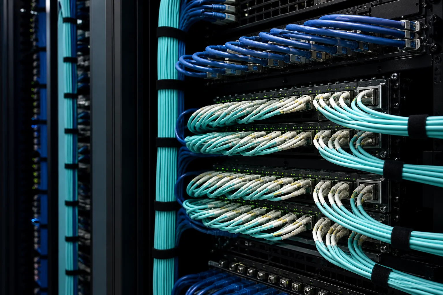
Essential Definitions and Terminology
Before diving into design, it’s critical to understand the fundamental terms used in fiber cabling. These definitions form the vocabulary for all subsequent discussions.
Fiber Types
- Single-mode fiber (SMF): A fiber with a small core (typically 9 µm) that allows only one mode of light to propagate. It supports very high bandwidth over long distances (up to tens of kilometers) and is used in telecom and data center interconnects.
- Multimode fiber (MMF): A fiber with a larger core (50 µm or 62.5 µm) that supports multiple light modes. It is cost-effective for short distances (up to a few hundred meters) and is common in data center horizontal cabling.
Connectors and Polarity
- Connector types: Common connectors include LC (Lucent Connector), SC (Subscriber Connector), and MPO (Multi-fiber Push On). LC is prevalent in data centers for its small footprint; MPO supports multiple fibers (e.g., 8, 12, 24) in a single connector, enabling high-density connections.
- Polarity: The arrangement of transmit and receive fibers in a multi-fiber system. Correct polarity ensures that signals travel from transmitter to receiver. Standards like TIA-568 define polarity methods (A, B, C) for MPO-based systems.
Cabling Components
- Patch cords: Flexible fiber cables with connectors on both ends, used for temporary or semi-permanent connections in patching areas.
- Trunk cables: Multi-fiber cables (often MPO-terminated) that run from the main distribution area to equipment distribution areas, reducing cable volume.
- Breakout cables: Cables that fan out from a multi-fiber connector to individual duplex connectors, enabling connection to standard transceivers.
- Fiber distribution frames (FDF) or panels: Enclosures that organize and protect fiber terminations, providing patching and splicing points.
Transceivers and Optical Specifications
- Transceivers: Devices that convert electrical signals to optical and vice versa. Common form factors include SFP, SFP+, QSFP, and QSFP-DD. They are rated for specific fiber types and distances (e.g., SR for short reach multimode, LR for long reach single-mode).
- Insertion loss: The attenuation of light caused by a connector or splice, measured in decibels (dB). Lower is better.
- Return loss: The amount of light reflected back toward the source, also in dB. Higher is better.
The Role of Fiber Cabling in Data Center Operations
Fiber cabling is not just a passive infrastructure; it is an active enabler of data center performance and agility. Its role extends beyond simple connectivity.
Supporting High Bandwidth and Speed
Modern data center applications—such as artificial intelligence, machine learning, and high-performance computing—demand massive bandwidth. Fiber cabling, especially single-mode, can support speeds of 400G and beyond, with future-proofing for 800G and 1.6T. Multimode fiber, while limited in distance, offers a cost-effective solution for intra-rack and adjacent-rack links.
Enabling Scalability and Flexibility
A well-designed fiber cabling system allows data centers to adapt to changing needs without major overhauls. Structured cabling—with defined zones and pathways—simplifies moves, adds, and changes (MACs). Using pre-terminated trunk cables and MPO connectors can reduce deployment time and minimize human error.
Ensuring Reliability and Manageability
Fiber is immune to electromagnetic interference and has a longer lifespan than copper. Proper cable management—including slack storage, bend radius protection, and labeling—ensures that the physical layer does not become a point of failure. Monitoring and testing are easier with fiber, as optical time-domain reflectometers (OTDRs) can pinpoint issues.
Key Engineering Decisions in Fiber Cabling Design
Designing a data center fiber cabling system involves a series of decisions that balance performance, cost, and future needs. These decisions are interdependent and should be made with a holistic view.
Choosing Fiber Type: Single-Mode vs. Multimode
This is the most fundamental choice. Multimode fiber (OM3, OM4, OM5) is cheaper for short distances (up to 100-150 meters for 100G) and uses lower-cost transceivers (VCSEL-based). Single-mode fiber (OS2) is more expensive per port but supports longer distances and higher speeds, making it essential for inter-building links and future high-speed applications. Many data centers adopt a hybrid approach: multimode for intra-rack and short links, single-mode for backbone and cross-connect.
Selecting Connector and Polarity Schemes
The connector choice affects density, ease of installation, and compatibility. LC duplex connectors are standard for most transceivers, but MPO is essential for high-density parallel optics (e.g., 40G, 100G, 400G). Polarity must be carefully planned, especially when using MPO-based trunk cables. Standards such as TIA-568 and ISO/IEC 11801 define polarity methods, but engineers must verify that the chosen method matches the transceivers and patch cords.
Designing the Topology: Structured vs. Point-to-Point
Structured cabling uses a hierarchical design with main distribution areas (MDA), horizontal distribution areas (HDA), and equipment distribution areas (EDA). This approach simplifies management and supports reconfiguration. Point-to-point cabling directly connects devices, which may reduce initial cost but complicates moves and increases cable congestion. For most data centers, a structured approach is recommended, especially in large facilities.
Considering Density and Cable Management
High-density fiber panels and MPO trunks can pack many fibers into a small space, but they require careful cable management to avoid congestion and maintain bend radius. Decisions include rack-mount vs. wall-mount panels, vertical vs. horizontal cable managers, and the use of breakout cassettes. The goal is to balance accessibility with density, ensuring that technicians can work without disturbing adjacent connections.
Planning for Migration and Future Upgrades
Data centers evolve. A migration plan should account for changes in speed (e.g., from 10G to 100G), new transceiver types, and potential shifts from multimode to single-mode. Using components that are backward compatible, such as MPO-16 or MPO-24 connectors, can ease transitions. Also, consider the lifecycle of cabling: fiber is typically installed for 15-20 years, so it must support future standards.
In summary, data center fiber cabling is a critical investment that requires careful planning. By understanding the terminology, the system’s role, and the key design decisions, engineers can build a cabling infrastructure that is robust, scalable, and ready for the future.
Major Fiber Cabling Architectures in Data Centers
Data center fiber cabling architectures have evolved from simple point-to-point links to structured, high-density designs that support current and future bandwidth demands. The three dominant architectures are:
- Structured Cabling: A hierarchical approach with permanent links from the equipment distribution area (EDA) to the main distribution area (MDA), using patch panels and cross-connects. It offers centralized management, easy moves/adds/changes (MACs), and supports both Top-of-Rack (ToR) and End-of-Row (EoR) topologies.
- Point-to-Point: Direct fiber runs between switches and servers, often used in small deployments or for specific high-performance links. It minimizes insertion loss but complicates scalability and troubleshooting.
- Leaf-Spine (Clos) Architecture: A two-layer network where every leaf switch connects to every spine switch, providing predictable latency and high bandwidth. This architecture relies heavily on structured cabling to manage the many interconnects.
Each architecture has tradeoffs in cost, flexibility, and performance. Structured cabling is the industry norm for enterprise and colocation data centers due to its manageability, while leaf-spine is the de facto standard for modern cloud and hyperscale facilities.
Topology Choices: ToR, EoR, and Middle-of-Row
Within structured cabling, the physical layout of fiber trunks and patch panels defines the topology:
- Top-of-Rack (ToR): Each rack has its own access switch, with fiber trunks running to a central distribution area. This reduces cable lengths and simplifies patching, but increases switch count and power density.
- End-of-Row (EoR): Switches are consolidated at the end of a row, serving multiple racks. This reduces switch count but requires longer fiber runs and more careful cable management.
- Middle-of-Row (MoR): A compromise, placing switches in a central cabinet within the row, balancing cable lengths and manageability.
The choice depends on rack density, cooling, and operational preferences. ToR is common for high-performance computing, while EoR suits lower-density environments.
Comparison of Cabling Architectures
| Architecture | Scalability | Manageability | Cost | Typical Use Case |
|---|---|---|---|---|
| Structured (ToR) | High | Excellent | Medium | Enterprise, cloud |
| Structured (EoR) | Medium | Good | Lower | Smaller data centers |
| Point-to-Point | Low | Poor | Low | Legacy, small labs |
| Leaf-Spine | Very High | Excellent | Higher | Hyperscale, high-performance |
This table highlights that while point-to-point is cheapest initially, it fails to scale. Structured and leaf-spine architectures, though more expensive upfront, provide long-term flexibility and lower operational overhead.
Selection Criteria for Data Center Fiber Cabling
Choosing the right cabling system involves balancing performance, cost, and future needs. Key criteria include:
- Bandwidth Requirements: Current and projected speeds (e.g., 400G, 800G) dictate fiber type and connector density. Single-mode fiber (OS2) supports longer distances and higher speeds, while multimode (OM4/OM5) is cost-effective for short reaches.
- Distance: Data center spans typically range from a few meters to a few hundred meters. Multimode is suitable for links under 100 meters at 400G, but single-mode is required for longer runs or future-proofing.
- Density and Space: High-density environments benefit from smaller connectors like SN or CS, and from high-fiber-count trunks (e.g., 24- or 32-fiber).
- Manageability: Structured cabling with color-coding and labeling simplifies MACs and troubleshooting.
- Standards Compliance: Adherence to TIA-942 and ISO/IEC 11801 ensures interoperability and reliability.
Fiber Type: Single-Mode vs. Multimode
The choice between single-mode and multimode is critical. Single-mode fiber (OS2) has a smaller core (9 µm) and supports higher bandwidth over longer distances, making it ideal for backbone links and future 800G+ speeds. Multimode (OM4/OM5) has a larger core (50 µm) and uses VCSEL transceivers, which are cheaper for short reaches (typically under 100 meters). However, multimode’s distance limits at higher speeds are a constraint. For example, at 400G, OM4 supports only 70 meters with parallel optics, while OS2 can go kilometers.
Many modern data centers are migrating to single-mode for all links to avoid re-cabling during upgrades, despite higher transceiver costs. This is a strategic decision based on total cost of ownership.
Connector and Polarity Considerations
Connector choice affects density and insertion loss. LC is the legacy standard, but SN and CS connectors offer double density, which is beneficial for high-port-count switches. Polarity must be managed carefully, especially with parallel optics (e.g., MPO-16). Using pre-terminated trunk cables with correct polarity (e.g., Method A, B, or C) reduces installation errors.
Performance Limits and Design Tradeoffs
Every cabling decision involves tradeoffs. Key limits and tradeoffs include:
- Insertion Loss: Each connection adds loss. A typical LC connection has ~0.3 dB loss, while MPO connectors may have ~0.5 dB. Budgeting for loss is essential to ensure link reliability. Standards like TIA-568 set maximum channel loss, but typical values are lower.
- Return Loss: High return loss (low reflectance) is important for high-speed transmission. Angled physical contact (APC) connectors provide better return loss than UPC, but are not compatible with UPC.
- Distance vs. Speed: Higher speeds reduce maximum distance for multimode. For example, 100G over OM4 supports 150 meters, but 400G only 70 meters. Single-mode eliminates this distance barrier.
- Density vs. Manageability: Ultra-high-density connectors (e.g., 16-fiber MPO) save space but require careful handling and may complicate polarity.
- Cost vs. Future-Proofing: Single-mode fiber and components cost more initially but avoid rip-and-replace for future upgrades. Multimode is cheaper upfront but may become obsolete sooner.
Design tradeoffs also include cable routing: overhead vs. underfloor. Overhead trays simplify airflow management but may complicate access; underfloor is easier to modify but can conflict with cooling.
Ultimately, the optimal design aligns with the data center’s operational strategy, balancing immediate budget with long-term agility. A well-planned cabling infrastructure is an investment that pays off through reduced downtime and simplified upgrades.
Planning Calculations: From Link Loss to Pathway Fill
Before installation begins, every data center fiber cabling design must be validated with concrete calculations. The two most important are the optical link loss budget and the pathway fill ratio. Both determine whether the final system will perform reliably under real-world conditions.
Link Loss Budget: The Math That Predicts Performance
A link loss budget is the sum of all insertion losses along the optical path, including connectors, splices, and the fiber itself. The calculated total must be less than the maximum channel insertion loss allowed by the applicable standard—typically the TIA-568 series for generic cabling or IEEE 802.3 for Ethernet applications. These standards define the maximum loss for a complete channel, but they do not dictate how you allocate that budget among components. That allocation is an engineering decision.
For example, in a typical duplex single-mode link, you might allocate 0.3 dB per mated connector pair and 0.1 dB per fusion splice, with fiber attenuation of 0.4 dB/km at 1310 nm and 0.2 dB/km at 1550 nm. In a 100-meter link with two connector pairs and no splices, the total loss would be 0.6 dB plus 0.04 dB, well within the 2.0 dB limit for a 10GBASE-LRM channel. But in a long campus link of 2 km, the fiber loss alone becomes 0.8 dB, and you must carefully budget for additional connectors or patch panels.
Always include a design margin—typically 1 to 3 dB—to account for future splices, aging components, and measurement uncertainty. The margin is not a standard requirement, but it is a best practice that prevents costly rework.
Pathway and Cable Fill: Avoiding the Tug-of-War
Cable trays, conduits, and innerducts have a maximum fill ratio defined by the National Electrical Code (NEC) for fire safety and by TIA-569 for telecommunications pathways. For example, NEC 392.22 limits cable tray fill to 50% for a single layer of cables, while TIA-569 recommends a 40% fill for conduit. These are normative requirements, not suggestions. Exceeding them can cause excessive cable strain, poor airflow, and difficulty pulling future cables.
When calculating fill, use the actual outer diameter of the cable, not the fiber count. A 24-fiber trunk cable may have a diameter of 6 mm, while a 12-fiber cable might be 4.5 mm. The difference in cross-sectional area is significant. For high-density areas, consider using smaller-diameter cables or pre-terminated trunk assemblies that can be routed without pulling tension.
A common field mistake is to assume that a 48-fiber trunk will fit in the same pathway as two 24-fiber trunks. It often does not, because the jacket and strength members add bulk. Always calculate the total area of all cables and compare it to the pathway cross-section, then apply the applicable fill limit.
Installation Implications: Pulling, Bending, and Managing the Physical Plant
The best-designed data center fiber cabling system fails if it is installed incorrectly. Physical stresses during pulling, bending, and fastening are the leading causes of latent fiber damage that only appears months later as intermittent errors.
Pulling Tension and Bend Radius: The Unseen Limits
Every fiber optic cable has a maximum tensile load during installation and a minimum bend radius. These values are specified by the cable manufacturer and are typically based on the fiber type and construction. For example, standard single-mode fiber can withstand 100 kpsi (689 MPa) of tensile stress, but the cable’s strength members determine the actual pulling limit. A typical 12-fiber indoor cable may have a maximum installation tension of 440 N (100 lbf), while a 144-fiber trunk might be rated at 1000 N (225 lbf).
The minimum bend radius is usually 10 times the cable diameter during installation and 15 times the diameter after installation. These are typical values, not universal standards. Always consult the manufacturer’s datasheet.
During pulling, use a swivel pulling eye and a tension meter. Never pull on the fiber itself. If you must pull around corners, use pulleys or lubricant to reduce friction. A common error is to pull a cable through a conduit with multiple bends without a pull box, causing the cable to exceed its bend radius and crack the fiber.
Managing Slack and Strain Relief
Once the cable is in place, proper slack management is essential. Leave at least 1 to 2 meters of slack at each end to allow for connector re-termination or relocation. In racks, use horizontal cable managers with sufficient depth to maintain the bend radius. Vertical cable managers should be sized to accommodate the number of cables without crushing them.
Strain relief is critical at termination points. Use cable ties with a torque limiter, or better, use hook-and-loop fasteners. Over-tightening a cable tie can crush the fiber and cause attenuation. In high-density environments, consider using pre-terminated trunk cables with factory-installed connectors, which eliminate field termination errors but require careful routing to avoid exceeding the bend radius.
Field Example: The Case of the Hidden Micro-Bends
In one data center, a 48-fiber trunk was installed in a cable tray that had a sharp edge. The installer used a J-hook to support the cable, but the hook was too small, creating a micro-bend at the point of contact. The link passed initial testing, but after a few months, error rates increased. OTDR testing revealed a 0.5 dB loss at the exact location of the J-hook. The fix was to replace the J-hook with a wider radius support. This illustrates why installation practices must be verified with testing after installation, not just during the design phase.
Testing and Quality Assurance: Proving Performance
Testing is the only way to ensure that the installed data center fiber cabling meets the design requirements. There are two main types of testing: Tier 1 (basic) and Tier 2 (extended).
Tier 1 Testing: The Pass/Fail Check
Tier 1 testing uses an optical loss test set (OLTS) to measure the end-to-end insertion loss of each fiber link. The measured loss is compared to the link loss budget. This test is required by TIA-568 for all installed cabling. It verifies continuity and polarity, and it catches gross errors like broken fibers or misaligned connectors.
A typical Tier 1 test involves a light source and power meter at each end. The tester must be calibrated to the same wavelength and connector type as the system. For multimode, use a mandrel to strip high-order modes. For single-mode, use a laser source.
Tier 2 Testing: The Diagnostic Tool
Tier 2 testing uses an OTDR to characterize the fiber link. The OTDR provides a graphical trace that shows the loss and reflectance of each event (connector, splice, bend). This test is not always required, but it is invaluable for troubleshooting and for documenting the installation’s quality. It can identify a bad splice, a cracked fiber, or a bend that is below the threshold of Tier 1 testing.
For example, an OTDR might reveal a 0.2 dB loss at a connector that is within the budget but is caused by a dirty endface. Cleaning the connector would reduce the loss to 0.1 dB, improving the margin. Without Tier 2 testing, this issue might go unnoticed until later.
Documentation and Certification
After testing, produce a certification report that includes the link loss measurements, OTDR traces, and a summary of the results. This report serves as a baseline for future troubleshooting and for validating the installation to the customer. Keep it in a central repository accessible to all stakeholders.
Also, label every cable and port clearly. Use a consistent labeling scheme that matches the design documentation. This is not a standard requirement, but it is essential for maintaining the system over its lifecycle.
Practical Field Caveats: Lessons from the Trenches
Even with careful planning and testing, issues arise. Here are some common pitfalls and how to avoid them.
Dirty Connectors: The Silent Killer
Dust and oil on connector endfaces are the leading cause of link failures. Always inspect connectors with a scope before mating, and clean them with a dry or wet cleaning kit. Never touch the endface with bare fingers. In high-density environments, use a one-click cleaner for efficiency.
Polarity Errors
In duplex systems, polarity errors are easy to make when using pre-terminated trunks with MPO connectors. Always verify polarity with a visual fault locator or a light source before connecting. Use a polarity tester that checks all fibers in a trunk.
Environmental Factors
Temperature and humidity can affect fiber performance. In data centers, the environment is usually controlled, but in outside plant or mixed-use facilities, be aware of the operating temperature range of the cable. Also, avoid running fiber near power cables to prevent electromagnetic interference, though fiber is immune to EMI, the metallic strength members can act as antennas.
Future-Proofing with Testing
Finally, remember that testing is not a one-time event. When you make changes to the cabling, retest the affected links. This ensures that the system continues to meet the design requirements and that you have an up-to-date baseline for troubleshooting.
By following these planning, installation, and testing practices, you can ensure that your data center fiber cabling is reliable, scalable, and ready for future upgrades.
Failure Modes and Common Mistakes in Data Center Fiber Cabling
Even with meticulous planning, fiber cabling systems can fail or underperform. Understanding the typical failure modes and frequent mistakes helps you avoid costly rework and downtime.
Physical Damage and Stress
The most common physical failures include:
- Micro-bends and macro-bends: Tight bends or crushing forces cause light to leak from the core, increasing attenuation. While macro-bends are visible, micro-bends often occur inside patch panels or cable trays.
- Excessive tensile stress: Pulling cables beyond their rated tension can break fibers or cause permanent elongation, leading to signal loss.
- Connector damage: Dust, scratches, or misalignment on ferrule end faces degrade optical performance. Even a single dirty connector can cause link failure.
Contamination and Environmental Factors
Dust and oils are the leading causes of intermittent or permanent failures. Connectors should always be capped when not in use, and inspection before mating is a best practice. Environmental factors such as temperature extremes, humidity, and vibration can also affect performance, especially in non-plenum spaces.
Documentation and Labeling Errors
Poor documentation leads to misidentification, incorrect patching, and extended troubleshooting. In a high-density environment, a single mislabeled fiber can cause hours of delay.
Common Mistakes in Design and Installation
- Ignoring polarity: For duplex and parallel optics, incorrect polarity prevents communication. Always follow TIA-568 or IEC standards for polarity schemes.
- Overfilling pathways: Exceeding recommended fill ratios makes cable pulling difficult and increases the risk of damage.
- Inadequate slack management: Too little slack makes re-termination impossible; too much slack creates bends and tangles.
- Skipping testing: Relying on manufacturer test reports instead of field testing can miss installation-induced faults.
Procurement Checklist for Data Center Fiber Cabling
When purchasing fiber cabling components, a structured checklist ensures you get the right products and avoid surprises.
Define Requirements
- Fiber type: OM3, OM4, OS2, or newer categories. Match the fiber to the transceiver type and distance.
- Connector type: LC, MPO, or other. Ensure compatibility with existing equipment.
- Performance class: Specify insertion loss and return loss limits per relevant standards (e.g., TIA-568.3-D).
- Environment: Plenum or riser rated jackets, indoor/outdoor, and temperature range.
Quality and Compliance
- Standards compliance: Verify that products meet applicable TIA, ISO/IEC, and Telcordia (GR-326 for connectors) requirements.
- Test reports: Request individual or lot test data for insertion loss and return loss.
- Warranty and support: Understand the warranty terms and technical support availability.
Logistics and Installation
- Lead times: Plan for manufacturing and shipping times.
- Cable lengths: Order appropriate lengths, accounting for service loops and routing.
- Packaging: Ensure reels or boxes are suitable for the installation method.
Lifecycle Maintenance: Keeping Performance Over Time
Fiber cabling is not a set-and-forget asset. Regular maintenance preserves performance and extends lifespan.
Inspection and Cleaning
Inspect connector end faces with a microscope before every mating. Clean with appropriate tools—dry cleaning is often sufficient, but wet cleaning may be needed for stubborn contamination. Never reuse wipes or swabs.
Testing and Documentation Updates
Periodic Tier 1 testing (e.g., with an optical loss test set) verifies that link loss remains within budget. Update documentation whenever changes are made, including new patch cords, moved connections, or replaced components.
Environmental Monitoring
Monitor temperature and humidity in data center spaces. Extreme conditions can degrade cable materials and connectors.
Managing Moves, Adds, and Changes (MACs)
Each MAC introduces risk. Always follow proper procedures: label, test, and document. Use a change management process to track all physical layer modifications.
Actionable Recommendations and Conclusion
To ensure a reliable, future-ready data center fiber cabling infrastructure, consider these practical steps:
- Design with margin: Build in extra link loss budget to accommodate aging, dirty connectors, and future splices.
- Invest in quality components: Cheap connectors or patch cords often lead to higher loss and more failures.
- Train your team: Ensure installers and technicians are certified in fiber handling, inspection, and testing.
- Use a robust documentation system: A structured cabling management software or detailed spreadsheets can save hours during troubleshooting.
- Plan for future upgrades: Consider higher fiber counts and MPO-based trunk cables to support 400G and beyond.
In conclusion, successful data center fiber cabling hinges on meticulous planning, disciplined installation, and ongoing maintenance. By understanding failure modes, following a rigorous procurement process, and committing to lifecycle care, you can build a physical layer that delivers high performance for years. Remember that the primary keyword—data center fiber cabling—is not just a product category but a discipline that integrates engineering, quality, and operational excellence. Apply these insights to your next project, and you will avoid the common pitfalls that plague many deployments.
Frequently Asked Questions
What are the main types of fiber optic cables used in data centers?
Data centers commonly use single-mode fiber (OS2) for long distances and multimode fiber (OM3, OM4, OM5) for shorter, high-bandwidth links within the facility.
What is the difference between structured and point-to-point cabling in data centers?
Structured cabling uses a centralized distribution area with patch panels and trunks, offering flexibility and easier management, while point-to-point cabling directly connects devices, which can be simpler but less scalable.
How do I choose between MPO and LC connectors for data center fiber cabling?
MPO connectors support high-density parallel optics (e.g., 40G, 100G, 400G) and reduce cable counts, while LC connectors are used for duplex connections and are common in legacy or lower-speed applications.
What are the key considerations for migrating from older cabling to new fiber infrastructure?
Key considerations include assessing current and future bandwidth needs, ensuring compatibility with existing equipment, planning for minimal downtime, and using proper labeling and documentation.
What is polarity and why is it important in fiber cabling?
Polarity ensures that transmit and receive signals align correctly between devices. In MPO systems, proper polarity (A, B, C methods) is critical to avoid signal reversal and connectivity issues.
How can I ensure my data center fiber cabling is scalable for future upgrades?
Design with higher fiber counts (e.g., 24 or 48 fibers per trunk), use modular components, and adopt standards like TIA-942 or ISO 24764 to accommodate evolving speeds and architectures.
What are the best practices for managing fiber cables in a high-density environment?
Use horizontal and vertical cable managers, maintain proper bend radius, segregate power and data cables, and implement color-coding and labeling for easy identification and maintenance.
Related In-Depth Guides
Continue with these focused engineering guides:







