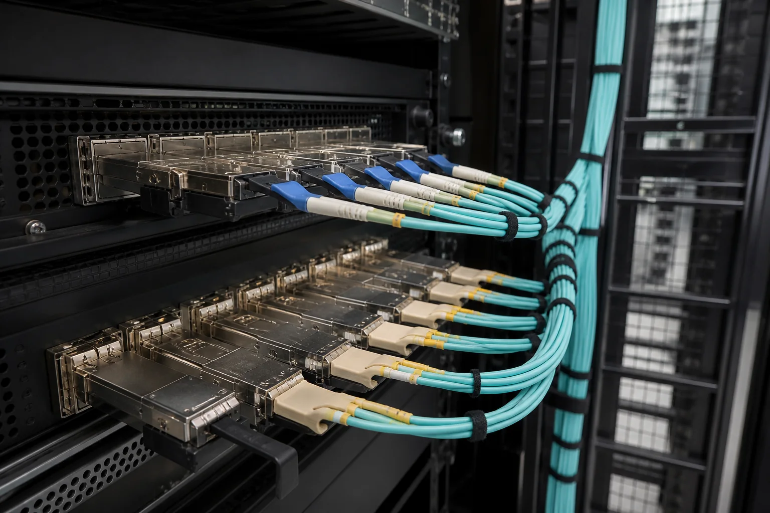
Summary: A passive fiber link cannot amplify light. When an optical loss test set reports negative insertion loss, first examine how its reference was established. A contaminated reference connection, a removed adapter, a changed launch condition or source drift can make a normal cable appear to have gain. This guide to negative fiber insertion loss troubleshooting focuses on the measurement setup before any installed cable is replaced.
The practical objective is not to force a positive number onto the screen. It is to demonstrate that the reported loss corresponds to the intended test boundary, with qualified reference cords and a reproducible setup. Preserve the original result so the commissioning record explains why a retest was necessary.
Start with the sign convention and measurement boundary
Check whether the instrument displays positive attenuation or signed relative power. For a positive-loss convention, insertion loss equals reference power in dBm minus measured power in dBm. A reference of −5.00 dBm and a measurement of −5.70 dBm therefore produce 0.70 dB loss. The dBm readings are absolute power levels; dB expresses their ratio.
A passive path cannot deliver more power than enters it. However, the stored reference and the later measurement may not represent identical source conditions or connection topology. The instrument reports that comparison, not a physical declaration that the cable is an amplifier. Record the source wavelength and meter setting before interpreting the sign.
Worked example: how reference contamination creates apparent gain
The following values are deliberately simplified teaching assumptions, not an OTDR trace, factory test or customer result. Assume a stable source, a correctly configured detector and negligible drift. A removable contaminated connection is accidentally included during referencing and then removed when the link is tested.
| Quantity | Assumed value | Meaning |
|---|---|---|
| Clean reference power | −5.00 dBm | Expected baseline for this example |
| Extra loss during referencing | 0.80 dB | Unwanted removable reference connection |
| Stored reference | −5.80 dBm | Baseline is now too low |
| Actual link loss | 0.45 dB | Illustrative intended test boundary |
| Received power during testing | −5.45 dBm | Clean baseline minus link loss |
| Displayed loss | −0.35 dB | −5.80 − (−5.45) |
The apparent gain is simply 0.45 − 0.80 = −0.35 dB. Nothing inside the cable generated power. The reference included a loss that the later measurement did not include. Resetting the reference correctly would restore a meaningful comparison, assuming the remaining setup stays stable.
This calculation is diagnostic, not a correction formula for real reports. Do not add an estimated connector loss to every reading. The contamination may change on each mating, and source or launch conditions may also have changed. Re-establish and verify the reference, then repeat the affected tests.
Choose the reference method before setting the pass limit
The FOA reference-cable guide explains that one-, two- and three-cord reference arrangements include different connections when zero is established. Connections included in that baseline are subtracted from the later measurement. Consequently, results obtained with different reference methods cannot be assumed to represent the same end-connection losses.
For compatible installed-link interfaces, use the one-cord arrangement prescribed by the instrument and project procedure. Where interfaces require another method, draw the reference and test configurations, identify which connections are excluded, and agree on the corresponding acceptance limit. EXFO’s reference-method explanation provides a useful comparison of these arrangements and the importance of reference connector condition.
The number of cords used to set the reference is not necessarily the number present during the actual link test. A receive cord may be added after referencing so that the far-end connection is included. Confusing those two stages is a common source of contradictory field instructions.
A controlled troubleshooting sequence
1. Preserve the evidence
Save the failing result, fiber identifier, wavelength, reference timestamp and equipment serial numbers. Photograph or sketch the current connections. Note whether the symptom affects one fiber, one wavelength or an entire batch. This establishes the likely scope of invalid results without assuming that every previous test is wrong.
2. Inspect the interfaces and verify the cords
Isolate the test path from active equipment and use appropriate video inspection tools. Inspect both mating sides, clean where necessary and reinspect. Confirm fiber type, connector interface and polish compatibility. Ordinary patch cords should not be treated as qualified test reference cords solely because they are new or individually packaged.
For procurement, our fiber optic patch cords and assemblies page describes configuration choices. A certification request should additionally specify reference-grade performance, compatibility with the selected tester and the verification records required. A general product listing alone does not establish suitability as a test reference cord.
3. Establish a fresh, documented reference
Follow the instrument’s warm-up and reference procedure at each required wavelength. Leave source-side connections undisturbed unless the procedure specifically allows reconnection. Verify the added receive cord as instructed. If the source-side cord, wavelength setup or launch configuration changes, determine whether a new reference is required before continuing.
4. Run a control, then the affected link
Test a known-good verification path with a documented expected range. Repeat the control after a controlled reconnect if the procedure permits it. If the control is unstable, troubleshoot the instruments and reference cords. If the control is stable but one installed link remains abnormal, inspect that link’s endpoints and configuration.
5. Decide the retest scope
Use the last successful reference verification as the starting point for review. Results collected after an unrecorded cord change or failed control may need repeating. Restore traceability by keeping superseded records, linking them to the replacement test and recording the specific correction—not merely “retested, passed.”
Symptom-to-action worksheet
| Observed pattern | First hypothesis to investigate | Controlled check |
|---|---|---|
| Similar negative offset on many fibers | Reference baseline or topology mismatch | Rebuild the prescribed reference and test a control |
| Only one connector changes on remating | Contamination, damage or mating variability | Inspect both faces and verify with qualified cords |
| Results drift over time | Source stability or changing environment | Check the reference and stabilization requirements |
| One wavelength behaves differently | Incorrect setting, reference or wavelength-dependent path | Verify each wavelength separately |
| Numbers vary around zero | Measurement uncertainty near a low-loss limit | Apply the documented instrument and project decision rule |
Do not confuse OLTS offsets with OTDR gainers
An OLTS measures end-to-end transmitted power. An OTDR infers events from returned backscatter, so a splice between fibers with different backscatter characteristics can appear to have gain in one direction. For that OTDR problem, bidirectional event analysis can be appropriate; it does not repair a faulty OLTS reference.
See our fiber optic installation and testing guide for the overall commissioning workflow and causes of high fiber insertion loss when a verified setup indicates genuine attenuation. Keep the present article focused on invalid or uncertain negative readings rather than general cable faults.
Acceptance: investigate, document, then release
Fluke Networks’ negative-loss guidance shows that its CertiFiber Pro treats sufficiently negative readings as a failure requiring corrective action. That product-specific behavior is not a universal threshold for every tester. Use the exact instrument manual, calibration status and project specification.
A defensible report includes the reference method, wavelength, test boundary, cord verification, control result and any retest history. Do not silently clamp negative readings to zero or repeatedly reseat connectors until a convenient number appears. Release the link only after the measurement method itself has been demonstrated to work.
Frequently Asked Questions
Can passive fiber really have negative insertion loss?
No. A passive cable does not generate optical power. A negative displayed loss means the measured power exceeds the stored reference under the current test conditions. Investigate the reference, connections, source stability and instrument uncertainty before accepting the result.
Should I replace the installed cable immediately?
No. First verify the measurement setup with clean, compatible test reference cords and a known-good control. A systematic negative offset across many fibers often points to the reference process. Retest the installed cable after the setup is verified.
Is the one-cord reference always possible?
Not always. Connector interfaces and instrument adapters can prevent a direct one-cord setup. Follow the applicable equipment instructions and project test method, document the selected reference topology, and apply the corresponding acceptance boundary.
Is negative OLTS loss the same as an OTDR gainer?
No. An OLTS compares received power against a stored reference. An OTDR estimates event loss from backscatter, and differing backscatter characteristics can create apparent gain at a splice. The causes and appropriate verification methods differ.
May I simply change a negative value to zero?
No. Keep the original result, correct or verify the reference, and repeat the affected measurements. A small near-zero negative result may reflect uncertainty, but its treatment must follow the tester guidance and agreed acceptance procedure rather than silent editing.