
When performing OTDR testing, the OTDR launch cable length is a critical parameter that directly affects measurement accuracy. In short, a launch cable (also called a pulse suppressor or launch fiber) must be long enough to allow the OTDR to recover from its own internal reflections and settle before the signal reaches the fiber under test. The typical minimum length is 100–200 meters, but the exact value depends on your OTDR’s dead zone specifications, the pulse width used, and the fiber type. This article explains how to determine the right length, the tradeoffs involved, and best practices for field testing.
What is a Launch Cable and Why is Length Important?
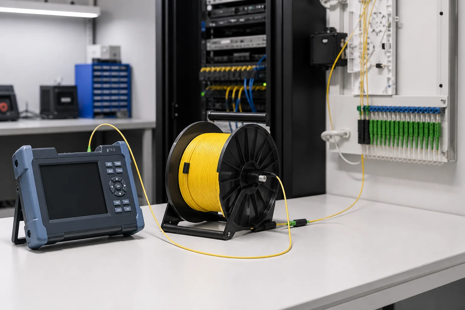
A launch cable is a short length of fiber optic cable that connects the OTDR to the fiber under test (FUT). It serves two main purposes: it moves the OTDR’s connector away from the measurement zone, and it absorbs the initial reflection and dead zone effects. Without a launch cable, the OTDR would be unable to measure the first connector or splice near the OTDR, and the loss at the launch connector would be incorrectly attributed to the FUT.
The length of the launch cable is important because it must exceed the OTDR’s dead zone—the distance after a reflection during which the OTDR cannot detect events. If the launch cable is too short, the dead zone will extend into the FUT, masking real events and causing inaccurate loss readings. Conversely, an excessively long launch cable adds unnecessary loss and cost, and may complicate testing in confined spaces.
Understanding OTDR Dead Zones
OTDRs have two types of dead zones: event dead zone and attenuation dead zone.
- Event dead zone is the minimum distance after a reflective event (like a connector) before another event can be detected. It is typically specified in meters and depends on the pulse width.
- Attenuation dead zone is the distance after a reflection before the OTDR can accurately measure loss. This is usually longer than the event dead zone.
The launch cable length must be at least as long as the attenuation dead zone to ensure that the OTDR can accurately measure the loss of the first connector in the FUT. For example, if your OTDR has an attenuation dead zone of 50 meters at a given pulse width, a 100-meter launch cable would be safe, but a 50-meter one might be marginal.
Manufacturers often specify dead zones in their datasheets, but these values are typically given for the shortest pulse width. When you increase the pulse width to test longer spans, the dead zones also increase. Therefore, you need to consider the maximum pulse width you will use for the test.
How to Calculate the Required Launch Cable Length
There is no universal formula, but a practical approach is:
- Determine the maximum pulse width you plan to use for the test.
- Find the attenuation dead zone specification for that pulse width from your OTDR manual.
- Multiply that dead zone by a safety factor of 1.5 to 2.0 to account for variations in fiber and connectors.
For example, if the attenuation dead zone at your chosen pulse width is 80 meters, a launch cable of 120–160 meters would be appropriate. Many field technicians use a standard 300-meter launch cable because it covers most pulse widths and provides a comfortable margin.
Additionally, consider the fiber type. Single-mode fibers (G.652) have lower attenuation than multimode fibers (G.651 or OM3/OM4), but the dead zone is more influenced by the OTDR’s optics than the fiber type. However, for multimode testing, the launch cable should match the fiber type to avoid differential mode delay issues.
Selection Criteria: Fiber Type, Connectors, and Length
When selecting a launch cable, consider the following:
- Fiber type: Match the launch cable to the fiber under test—single-mode for single-mode, multimode for multimode. Using a single-mode launch cable on multimode fiber will yield incorrect results.
- Connector types: Ensure the launch cable has the correct connector on each end. The OTDR end should match your OTDR’s output port, and the FUT end should match the connector type of the fiber you are testing (e.g., SC, LC, FC).
- Length: As discussed, choose a length that exceeds the dead zone with margin. Common lengths are 100 m, 200 m, 300 m, 500 m, and 1000 m. For most outside plant (OSP) testing, 300 m is a safe choice.
- Quality: The launch cable should have low insertion loss and high return loss to minimize its impact on measurements. Look for cables with premium connectors and good polishing.
Design Tradeoffs: Long vs. Short Launch Cables
Choosing the launch cable length involves tradeoffs:
| Aspect | Short Launch Cable (e.g., 100 m) | Long Launch Cable (e.g., 300 m+) |
|---|---|---|
| Dead zone coverage | May be insufficient for long pulse widths | Covers most pulse widths |
| Portability | Easier to carry and deploy | Bulky and heavier |
| Cost | Lower cost | Higher cost |
| Loss contribution | Lower loss | Higher loss (but minimal for single-mode) |
| Flexibility | Limited to short-range tests | Suitable for various test scenarios |
For most applications, a 300-meter launch cable strikes a good balance. However, if you frequently test short jumper cables or inside data centers, a 100-meter launch cable may be sufficient. For long-haul or high-pulse-width testing, a 500-meter or even 1000-meter launch cable might be necessary.
Installation and Handling Considerations
Proper handling of launch cables ensures accurate and repeatable measurements:
- Cleanliness: Always clean the connectors on the launch cable and the OTDR before mating. Dirty connectors are a common source of measurement errors.
- Bend radius: Avoid bending the launch cable below its minimum bend radius, as this can cause loss and affect measurements. Use a cable reel or storage spool.
- Secure connections: Ensure that the connectors are fully seated and tightened to avoid intermittent reflections.
- Labeling: Clearly label the launch cable with its length and type to avoid confusion in the field.
When deploying the launch cable, keep it as straight as possible and avoid kinks. If you are testing in a confined space, consider using a shorter launch cable with a known dead zone, but verify that it meets the required length for your test.
Testing and Quality Assurance
To ensure reliable results, follow these testing practices:
- Perform a reference test with the launch cable alone to establish a baseline. This helps identify any issues with the launch cable itself.
- Use a receive cable at the far end of the FUT to measure the loss of the last connector accurately.
- Set the OTDR’s refractive index to match the fiber type (e.g., 1.4682 for G.652 single-mode).
- Choose an appropriate pulse width and averaging time to balance resolution and dynamic range.
Quality assurance also involves regular inspection of the launch cable’s connectors and fiber. Over time, connectors can become worn or contaminated, degrading performance. Replace launch cables that show high insertion loss or poor return loss.
Common Mistakes and How to Avoid Them
Several pitfalls can compromise OTDR measurements:
- Using a launch cable that is too short: This is the most common mistake. It leads to inaccurate loss readings on the first few events.
- Mismatching fiber types: Using a multimode launch cable on single-mode fiber (or vice versa) produces meaningless results.
- Ignoring pulse width: Failing to account for how pulse width affects dead zones can result in insufficient launch cable length.
- Poor connector hygiene: Dirty connectors cause reflections that can skew measurements.
- Not using a receive cable: Without a receive cable, the loss of the last connector cannot be measured accurately.
To avoid these mistakes, always verify the launch cable length against the OTDR’s specifications for the pulse width you are using, and maintain a clean work environment.
Procurement Checklist for Launch Cables
When purchasing launch cables, consider the following checklist:
- Fiber type (single-mode or multimode) and compatibility with your test fiber.
- Connector types on both ends (e.g., SC/APC to SC/APC).
- Length (based on your dead zone requirements).
- Insertion loss and return loss specifications.
- Durability and ruggedness for field use.
- Certification and quality standards (e.g., ISO/IEC).
For a variety of fiber optic tools and accessories, you can explore our fiber tools collection to find launch cables and other testing equipment.
Conclusion and Practical Recommendations
In summary, the OTDR launch cable length is not a one-size-fits-all value. It depends on your OTDR’s dead zone, the pulse width, and the fiber type. A practical starting point is a 300-meter single-mode launch cable, which covers most field testing scenarios. For multimode or short-reach applications, a 100-meter cable may suffice, but always verify against your equipment’s specifications.
Remember to maintain your launch cables, clean connectors, and follow standardized testing procedures. For more information on fiber testing standards, refer to resources like The Fiber Optic Association’s OTDR testing guide and relevant ITU-T G.652 recommendations.
If you need assistance selecting the right launch cable for your projects, our team at Liqiba is ready to help. We also offer quality assurance services—learn more about our quality commitment.
Frequently Asked Questions
What is the minimum OTDR launch cable length?
The minimum length is typically 100 meters, but it must be longer than the OTDR's attenuation dead zone at the chosen pulse width. For most OTDRs, a 100-meter cable is sufficient for short pulse widths, but 300 meters is recommended for versatility.
Can I use a longer launch cable than necessary?
Yes, you can use a longer cable, but it adds extra loss and may be less convenient. However, it provides more margin and can accommodate different pulse widths without changing cables.
Does the launch cable length affect accuracy?
Yes, if the launch cable is too short, the OTDR's dead zone will mask the first events, leading to inaccurate loss measurements. A properly sized launch cable ensures accurate measurement of the first connector and splice.
Can I use the same launch cable for single-mode and multimode?
No, you must use a launch cable that matches the fiber type of the fiber under test. Using a single-mode launch cable on multimode fiber will produce incorrect results due to modal dispersion.
How do I determine the right launch cable length for my OTDR?
Check your OTDR's specifications for the attenuation dead zone at the pulse widths you plan to use. Multiply that dead zone by 1.5 to 2.0 to get a safe length. For example, if the dead zone is 80 meters, use a 120-160 meter cable.
What is the difference between a launch cable and a receive cable?
A launch cable connects to the OTDR and the fiber under test to eliminate dead zone effects. A receive cable connects to the far end of the fiber under test to measure the loss of the last connector. Both are used together for accurate end-to-end testing.
Can I use a launch cable with a different connector type than my OTDR?
Yes, you can use adapter cables, but it's best to have a launch cable with the correct connector on the OTDR end. Using adapters can introduce additional loss and reflections, affecting accuracy.
Complete topic guide: Fiber Optic Installation and Testing: Complete Guide.







