
FTTH network design is the process of planning a fiber-to-the-home infrastructure that delivers reliable, high-bandwidth connectivity from a central office or point of presence to individual residences. A successful design balances technical performance, cost, and scalability, ensuring that every subscriber receives consistent optical signal quality within the network’s operational limits. This guide walks you through the core architecture choices, loss budget calculations, and deployment considerations that define a robust FTTH network.
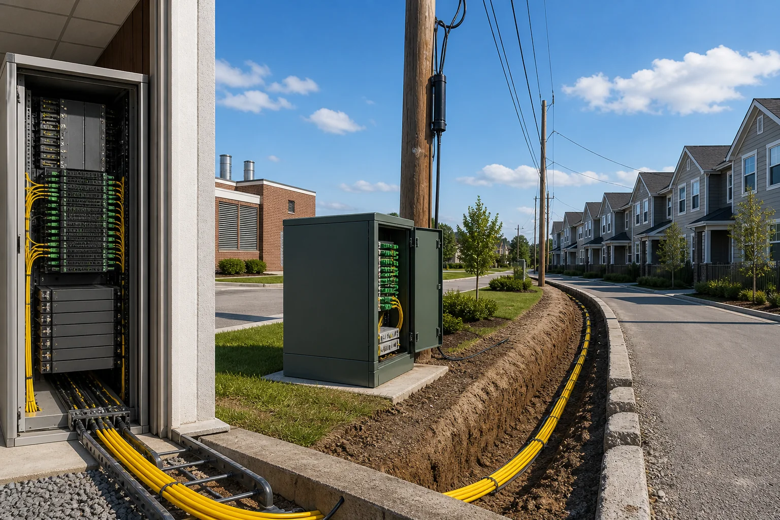
Essential FTTH Terminology
Before diving into design decisions, it’s critical to understand the vocabulary used across the industry. These terms appear throughout planning documents, vendor specifications, and field discussions.
Optical Distribution Network (ODN)
The ODN is the physical fiber infrastructure between the optical line terminal (OLT) and the optical network terminal (ONT) at the subscriber’s premises. It includes feeder cables, distribution cables, drop cables, splitters, and all associated connectors and splices.
Splitter
A passive optical component that divides a single optical signal into multiple paths. Splitters are characterized by their split ratio (e.g., 1:8, 1:16, 1:32) and are used to share the OLT port among multiple subscribers.
OLT and ONT
The OLT resides at the central office or headend and manages the network. The ONT is installed at the subscriber’s location, converting optical signals to electrical ones for in-home devices. Together, they define the active endpoints of the passive optical network (PON).
Fiber Types
Single-mode fiber (SMF) is the standard for FTTH due to its low attenuation and high bandwidth. Within SMF, ITU-T G.652.D is the most common recommendation for outside plant, while G.657.A1 or A2 fibers offer improved bend resistance for tight indoor spaces.
Loss Budget
The total allowable optical power loss between the OLT transmitter and the ONT receiver, expressed in decibels (dB). It accounts for fiber attenuation, connector losses, splice losses, and splitter losses, and must be within the dynamic range of the optical transceivers.
The Role of the FTTH Network in Modern Connectivity
FTTH networks serve as the backbone of residential broadband, enabling symmetrical gigabit speeds, low latency, and future-proof capacity. Unlike copper-based technologies (DSL or cable), fiber is immune to electromagnetic interference and offers virtually unlimited bandwidth potential.
In a typical FTTH deployment, the OLT connects to a passive optical splitter, which fans out to multiple ONTs. This architecture reduces the number of active components and central office ports, lowering operational costs while maintaining high reliability. The design must ensure that the optical signal reaching each ONT remains above the receiver sensitivity threshold, even under worst-case conditions.
Engineers must also consider the network’s scalability. A well-designed FTTH network can accommodate future upgrades, such as increasing split ratios or migrating to higher-speed PON standards (e.g., from GPON to XGS-PON), without replacing the entire fiber plant.
Key Engineering Decisions in FTTH Network Design
Every FTTH project requires a series of deliberate choices that affect performance, cost, and maintainability. The following are the primary decisions you’ll face.
Choosing a PON Architecture
The two main architectures are point-to-point (P2P) and point-to-multipoint (P2MP) using passive splitters. P2P provides dedicated fiber per subscriber, offering maximum security and simplicity but requiring more fiber and central office ports. P2MP, used in PON systems, shares fiber and ports, reducing infrastructure costs but introducing splitter losses and shared bandwidth.
For most residential deployments, P2MP with a splitter hierarchy (e.g., a 1:4 splitter at the central office followed by 1:8 at the distribution point) is common. The optimal split ratio depends on the required bandwidth per subscriber and the optical budget available.
Determining Splitter Placement
Splitters can be centralized in a single location (e.g., a fiber distribution hub) or distributed throughout the network. Centralized splitting simplifies management and testing but requires longer drop fibers. Distributed splitting reduces drop cable lengths but increases the number of splice points and enclosures.
Your choice affects the loss budget and the flexibility of the network. Centralized splitting is easier to maintain, while distributed splitting can be more cost-effective in low-density areas.
Selecting Fiber and Cable Types
For outdoor sections, standard single-mode fiber (G.652.D) is typical, but in high-density urban environments, bend-insensitive fiber (G.657.A2) may be necessary to handle tight bends in ducts or microtrenches. For indoor drop cables, G.657.A1 is often used due to its flexibility and resistance to bending during installation.
Cable construction also matters: loose-tube cables are suitable for outdoor aerial or duct installation, while tight-buffered cables are easier to terminate indoors. The choice impacts installation time and long-term reliability.
Planning the Loss Budget
The loss budget is a critical calculation that ensures the system operates within the optical power limits of the transceivers. It is not a fixed standard but is derived from the specifications of the OLT and ONT optics. For example, a typical GPON system might have a loss budget of 28 dB, but this varies by vendor and class (e.g., Class B+ or C+).
To calculate the loss budget, sum the worst-case losses from all components: fiber attenuation (typically 0.35 dB/km at 1310 nm and 0.25 dB/km at 1550 nm for G.652.D), connector losses (0.5 dB per connector pair), splice losses (0.1 dB per splice), and splitter losses (e.g., 3.5 dB for a 1:2 splitter, 7 dB for a 1:4, 10.5 dB for a 1:8, etc.). You must also include a design margin (often 2-3 dB) to account for future repairs, aging, and measurement uncertainty.
Ensure the total calculated loss is less than the system’s allowable loss. If it exceeds, you may need to reduce split ratios, shorten fiber lengths, or use higher-quality components.
Considering Deployment Topologies
FTTH networks can be deployed in several topologies: point-to-point, star, bus, or ring. In practice, PON networks use a star topology with splitters, but the physical routing of cables can be aerial, underground, or a mix. The choice depends on local regulations, existing infrastructure, and cost.
Aerial deployment is faster and cheaper but more exposed to weather and physical damage. Underground deployment is more durable but requires trenching or microtrenching, which is disruptive and expensive. Many operators use a combination, with aerial in rural areas and underground in urban centers.
Planning for Future Upgrades
Design with headroom: choose components that support higher split ratios or multiple wavelengths. For instance, using G.652.D fiber ensures compatibility with future PON standards that may use different wavelengths. Also, consider installing extra fibers (e.g., 10-20% spare) to accommodate future demand without re-cabling.
Document the network thoroughly, including fiber maps, splice records, and test results. This documentation is invaluable for troubleshooting and future expansion.
By addressing these decisions systematically, you can create an FTTH network design that meets current needs while remaining adaptable for years to come.
FTTH Network Architectures: Point-to-Point vs. PON
FTTH network design begins with a fundamental choice between two architectural families: point-to-point (P2P) and passive optical network (PON). In a P2P architecture, each subscriber has a dedicated fiber running from the central office (CO) to the premises. This offers maximum bandwidth and isolation but requires a large amount of fiber and active ports at the CO. PON, by contrast, uses a single feeder fiber from the CO to a passive splitter, which then distributes the signal to multiple subscribers. PON is the dominant choice for residential and mixed-use deployments due to its lower fiber count and shared infrastructure costs.
Within PON, several standardized variants exist, including GPON (Gigabit PON), EPON (Ethernet PON), and the newer XGS-PON and 10G-EPON. These differ in data rates, framing, and compatibility. The choice of PON technology affects the loss budget, split ratio, and future upgrade path. For example, XGS-PON offers symmetric 10 Gbps capacity, while GPON provides 2.5 Gbps downstream and 1.25 Gbps upstream. These are normative capabilities defined by ITU-T and IEEE standards.
PON Variants and Their Role in FTTH Network Design
GPON is widely deployed and supports split ratios up to 1:64 or 1:128, depending on the loss budget and reach. EPON, standardized by IEEE, typically supports 1:32 splits. XGS-PON and 10G-EPON are designed for higher bandwidth and can support similar split ratios with appropriate optical budgets. The selection of a PON variant is often driven by existing infrastructure, service requirements, and cost. Many operators choose a technology that allows coexistence with legacy systems, such as using WDM multiplexers to run GPON and XGS-PON on the same fiber.
Comparison of FTTH Architectures
The table below summarizes key characteristics of the main FTTH network design architectures. Note that values such as split ratios and reach are typical engineering targets, not absolute limits—actual performance depends on fiber quality, connector losses, and other factors.
| Architecture | Fiber per Subscriber | Active Equipment | Typical Split Ratio | Typical Reach | Bandwidth Capacity | Best Fit |
|---|---|---|---|---|---|---|
| Point-to-Point (P2P) | 1 dedicated fiber | 1 port per subscriber at CO | N/A | Up to 10 km (or more with longer-reach optics) | Unlimited (depends on optics) | Enterprise, high-density urban, or low-subscriber-count areas |
| GPON | Shared (1:32 or 1:64) | 1 OLT port per PON | 1:32 to 1:64 | Up to 20 km | 2.5 Gbps down / 1.25 Gbps up | Residential, mixed-use |
| EPON | Shared (1:16 or 1:32) | 1 OLT port per PON | 1:16 to 1:32 | Up to 20 km | 1 Gbps symmetric | Residential, especially in Asia |
| XGS-PON | Shared (1:32 to 1:64) | 1 OLT port per PON | 1:32 to 1:64 | Up to 20 km | 10 Gbps symmetric | High-bandwidth residential, business |
| 10G-EPON | Shared (1:32 to 1:64) | 1 OLT port per PON | 1:32 to 1:64 | Up to 20 km | 10 Gbps down / 1 Gbps up (asymmetric) or 10G symmetric | High-bandwidth residential, business |
Selection Criteria for FTTH Network Design
Choosing the right architecture requires balancing several factors: subscriber density, expected bandwidth demand, fiber availability, and budget. A structured decision process can help.
- Subscriber density: In dense urban areas where many subscribers are near the CO, P2P may be feasible but costly in fiber. PON reduces fiber count significantly.
- Bandwidth requirements: If future services demand symmetric multi-gigabit speeds, XGS-PON or 10G-EPON are better suited than GPON.
- Existing infrastructure: If fiber is already deployed in a point-to-point manner, upgrading to PON may require new splitters and OLT ports.
- Cost per subscriber: PON typically has lower cost per subscriber due to shared feeder fiber and OLT ports.
- Scalability: PON allows adding subscribers by increasing split ratio (within loss budget limits) or adding new PON ports.
Decision Table for Architecture Selection
| Scenario | Recommended Architecture | Rationale |
|---|---|---|
| Low-density rural area with long distances | P2P or GPON with low split ratio | P2P avoids splitter losses; GPON with 1:8 or 1:16 can extend reach. |
| Urban multi-dwelling units (MDUs) | GPON or XGS-PON with centralized splitter | High density, shared splitter in building reduces fiber runs. |
| Business customers needing dedicated bandwidth | P2P or XGS-PON with low split ratio | P2P offers dedicated fiber; XGS-PON can provide symmetric 10G with lower split. |
| Greenfield residential development | GPON or XGS-PON with centralized splitter | Cost-effective, future-proof for higher speeds. |
Performance Limits and Design Tradeoffs
Every FTTH network design involves tradeoffs among reach, split ratio, and bandwidth. The loss budget is the primary constraint: each splitter and fiber splice introduces loss, reducing the optical power available at the ONT. Standards such as ITU-T G.984 (GPON) and G.9807 (XGS-PON) define classes (e.g., B+, C+) that specify allowable loss ranges. These are normative requirements that must be met to ensure proper operation.
Increasing the split ratio reduces the power per subscriber, limiting reach. Conversely, lowering the split ratio allows longer distances but requires more OLT ports and fiber. Bandwidth is shared among subscribers in a PON, so a high split ratio reduces per-subscriber throughput during peak usage. This is a statistical multiplexing tradeoff: with many subscribers, the probability of all demanding peak bandwidth simultaneously is low, but the operator must plan for realistic usage patterns.
Another tradeoff involves splitter placement. Centralized splitting (one splitter at the CO or a cabinet) simplifies management but uses more feeder fiber. Distributed splitting (splitters closer to subscribers) reduces feeder fiber but complicates testing and troubleshooting. The choice affects the loss budget and the ability to upgrade to higher split ratios later.
Finally, the network designer must consider future upgrades. Choosing a PON technology that supports wavelength overlay (e.g., coexisting GPON and XGS-PON) allows migration without re-cabling. However, this requires additional optical components and may increase insertion loss. The design must therefore balance current needs with a reasonable upgrade path, without over-engineering for speculative demands.
From Paper to Field: Planning Calculations That Survive Contact
An FTTH network design that looks flawless in a spreadsheet can fail on site if the planning calculations ignore real-world conditions. The loss budget is the backbone, but it must be complemented by physical route surveys, splice planning, and installation constraints. This section walks through the calculations that matter, the installation implications they create, and the testing regimen that proves the network works.
Route Survey and Cable Length Estimation
Before any cable is ordered, a route survey must confirm distances, duct availability, and access points. The survey should record not just the straight-line distance but the actual cable path, including bends, vertical rises, and slack loops. A common mistake is to underestimate cable length by ignoring slack—typically 5–10% is added for slack and routing contingencies, though this is an engineering practice, not a standard. For aerial plant, sag and pole clearances add length; for buried plant, trench curves and manhole loops do the same. The survey also identifies potential damage risks, such as sharp bends or rodent activity, which influence cable selection and protection.
Splice and Connector Loss Planning
The loss budget must allocate realistic values for splices and connectors. While standards like ITU-T G.671 set maximum allowable attenuation for individual components, typical field values are lower: fusion splices often achieve 0.02–0.05 dB, and connectors 0.2–0.5 dB. However, planning should use conservative figures—for example, 0.1 dB per splice and 0.5 dB per connector—to accommodate less-than-perfect field conditions. Count every splice point: at the OLT, at each splitter, at distribution points, and at the ONT. A 1:32 splitter with 2 splices and 2 connectors can add 1.2–2.0 dB beyond the splitter loss itself. These numbers are typical, not normative, but they illustrate why meticulous counting is essential.
Splitter Placement and Power Budget Verification
Splitter placement determines the optical path length and loss distribution. Centralized splitting in a central office reduces field splicing but requires longer distribution cables; distributed splitting brings fibers closer to subscribers but adds splice points. Use the loss budget to verify that the chosen placement meets the required power margin. For example, a GPON system with a 28 dB loss budget (typical for Class B+ optics) must accommodate all losses from OLT to ONT. If the total calculated loss exceeds the budget, adjust splitter placement or choose a higher-power optical class. Always include a margin—often 2–3 dB—for aging, temperature effects, and future maintenance, though this is a design choice, not a standard requirement.
Installation Implications: What the Design Means for the Crew
The design choices directly affect installation methods, labor, and time. A design that minimizes fiber counts may reduce material cost but increase splicing complexity. Conversely, a design with more fibers can simplify splicing but raise cable costs. The installation team must interpret the design intent correctly to avoid errors.
Duct, Microduct, and Aerial Installation
In duct networks, the cable must be pulled with proper tension and bend radius. The design should specify maximum pulling length—often 100–200 meters between access points, though this varies with duct condition and cable type. Microducts allow blown fiber installation, which can cover longer distances without intermediate splicing, but require specialized equipment and careful route planning to avoid blockages. Aerial installation demands attention to sag and wind loading; the design must specify pole spacing and hardware. Each method has implications for the loss budget: aerial cables may suffer from temperature-induced attenuation changes, and duct cables may experience micro-bending if pulled too tightly.
Splice Enclosures and Fiber Management
Every splice point requires an enclosure that protects the splice and manages fiber slack. The design must specify the type and capacity of enclosures—for example, a dome closure for buried plant or a cabinet for aerial. Overcrowding an enclosure can lead to micro-bending and high loss. The design should also define splice tray layouts and fiber routing within the enclosure to ensure bend radii are maintained. A common field issue is improper fiber slack storage, which can cause attenuation spikes. The design should include clear instructions for slack storage and splice tray organization.
Drop Cable and In-Home Installation
The drop cable from the distribution point to the subscriber premises is often the most vulnerable segment. It must be rugged enough for outdoor exposure yet flexible enough for indoor routing. The design should specify drop cable type—for example, a flat dielectric cable for aerial or a round cable for duct—and the transition point to indoor fiber. In-home installation involves routing fiber to the ONT, often with tight bends. The design should specify minimum bend radius for the drop cable and indoor fiber, and the installer must use bend-insensitive fiber if necessary. The loss budget should include the drop and in-home connectors, which are typically 0.5 dB each.
Testing and Quality Assurance: Proving the Network
Testing is not optional; it is the only way to verify that the installed network meets the design loss budget and operates reliably. The testing regimen follows the installation phases and uses standardized procedures.
OTDR Testing and Event Interpretation
After splicing, an Optical Time-Domain Reflectometer (OTDR) is used to measure loss and locate events. The OTDR trace shows the attenuation along the fiber and identifies splices, connectors, and breaks. The design should specify OTDR test wavelengths—typically 1310 nm and 1550 nm for single-mode—and the expected event loss thresholds. A splice with loss above 0.1 dB may need redoing, though acceptable limits depend on the overall budget. The OTDR also reveals reflective events, such as connectors, and non-reflective events, such as splices. Interpreting OTDR traces requires skill; a bend that causes loss may appear as a gradual slope rather than a discrete event. The design should include a testing plan that defines where to test—at the OLT, at splitters, and at the ONT—and what the pass/fail criteria are.
Insertion Loss and Power Meter Testing
End-to-end insertion loss is measured with a light source and power meter. This test verifies that the total loss is within the budget. For a PON, testing each ONT path individually is necessary, as the splitter creates multiple paths. The test should be performed after all splicing and connectorization is complete. The measured loss should align with the calculated loss; a significant discrepancy indicates a problem, such as a bad splice or a damaged fiber. The design should specify acceptable loss ranges based on the budget and the optical class of the system.
Documentation and As-Built Records
Quality assurance extends beyond testing to documentation. The design must include a plan for recording as-built information: actual cable lengths, splice locations, connector types, and test results. This documentation is vital for future maintenance and upgrades. The design should specify a documentation format—for example, a GIS database or spreadsheets—and the level of detail required. Without accurate as-built records, troubleshooting becomes guesswork, and future expansions are hampered.
Field Examples and Caveats: Lessons from the Trenches
Real-world installations often reveal gaps between design and practice. Here are common pitfalls and how to avoid them.
Example: Underestimating Splice Loss
A design for a GPON network with a 28 dB budget allocated 0.05 dB per splice, assuming perfect fusion. In the field, a crew working in dusty conditions achieved 0.15 dB per splice on average. With 10 splices in the path, the extra 1.0 dB pushed the total loss to 27.5 dB, leaving only 0.5 dB margin—below the recommended 2–3 dB. The network passed initial tests but failed during high-temperature summer months. The lesson: use conservative splice loss estimates and require re-splicing if actual losses exceed the plan.
Example: Bend Radius Violations in Drop Cables
In a residential deployment, installers routed drop cables around tight corners in attics, violating the 30 mm bend radius of the standard fiber. The OTDR showed high loss at those points, and the network had intermittent failures. The fix was to use bend-insensitive fiber for drops and to train installers on bend radius requirements. The design should explicitly state bend radius limits and provide guidance for tight spaces.
Caveat: Testing at the Wrong Wavelength
Some installers test only at 1550 nm, but the system may operate at 1310 nm for upstream. Losses can differ between wavelengths, especially at bends and splices. Always test at both wavelengths, or at least at the operational wavelengths, to ensure the network performs as designed.
Caveat: Ignoring Connector Contamination
Dirty connectors are a leading cause of high loss and reflectance. Even a tiny particle can cause 0.5 dB loss or more. The design should include a cleaning protocol: inspect every connector with a scope, clean with appropriate tools, and cap when not in use. This is a simple step that prevents many field issues.
In summary, an FTTH network design is only as good as its execution. Planning calculations must incorporate realistic field values, installation methods must respect physical limits, and testing must verify every link. By anticipating these practical aspects, you can deliver a network that not only meets the loss budget but also stands the test of time.
Failure Modes and Common Mistakes in FTTH Network Design
Even a well-planned FTTH network can suffer from avoidable issues. Understanding typical failure modes helps you design for reliability and troubleshoot effectively.
Optical Failure Modes
- Excessive attenuation: Often caused by poor splicing, dirty connectors, or tight bends. While standards define maximum link loss, a good design keeps margins for aging and future splices.
- Reflectance: High reflectance at connectors or mechanical splices can disrupt PON transmission. Use angled physical contact (APC) connectors where required by the system design.
- Fiber breaks: Usually due to mechanical stress, rodent damage, or installation errors. Proper routing and protection reduce risk.
Common Design and Installation Mistakes
- Underestimating splice loss: Field splices often have higher loss than theoretical values. Always include realistic splice loss in your budget.
- Ignoring connector contamination: Dust or oil on connectors is a leading cause of intermittent failures. Implement inspection and cleaning procedures.
- Bend radius violations: Especially in drop cables and patch panels, sharp bends cause loss and potential breakage. Enforce minimum bend radius during installation.
- Incorrect splitter placement: Placing splitters too far from subscribers increases drop length and loss. Balance splitter location with cabinet space and power budget.
- Poor documentation: Inaccurate as-built records make future maintenance difficult. Ensure documentation is updated after every change.
Procurement Checklist for FTTH Network Components
A structured procurement process ensures you get compatible, quality components. Use this checklist as a starting point.
Cables and Fibers
- Fiber type (e.g., G.652.D for standard single-mode) and count.
- Cable construction: loose tube, central tube, or ribbon; suitable for duct, aerial, or direct burial.
- Flame-retardant ratings for indoor sections (e.g., OFNR, OFNP) as required by local codes.
- Length markings and packaging for easy handling.
Passive Components
- Splitters: type (PLC or FBT), split ratio, and connector type (SC/APC typical).
- Connectors and adapters: grade, ferrule material, and insertion loss specifications.
- Splice trays, enclosures, and patch panels: capacity, sealing, and fiber management features.
- Drop cables: ruggedized or indoor, with appropriate connector pre-termination.
Active Equipment (If Procured Separately)
- OLT and ONT: PON standard (e.g., GPON, XGS-PON), port density, and power budget.
- Optical power meters, OTDRs, and visual fault locators for testing.
Vendor and Quality Considerations
- Request datasheets and verify compliance with relevant standards (e.g., ITU-T, IEC).
- Check for environmental ratings (e.g., IP ratings for outdoor enclosures).
- Ask for test reports and warranty terms.
- Ensure spare parts and consumables (e.g., splice sleeves, cleaning supplies) are available.
Lifecycle Maintenance: Keeping the Network Healthy
FTTH networks are long-term assets. Regular maintenance prevents degradation and extends service life.
Preventive Maintenance
- Schedule periodic inspections of aerial and underground plant.
- Clean connectors and inspect them with a scope before every reconnection.
- Monitor optical power levels at key points to detect gradual loss increases.
- Review alarm logs from OLT for recurring issues.
Corrective Maintenance
- Keep spare fibers and components on hand for quick repair.
- Use OTDR to locate faults accurately before dispatching crews.
- Maintain a log of all repairs and updates to as-built documentation.
End-of-Life Considerations
- Plan for technology upgrades (e.g., from GPON to XGS-PON) without replacing the passive infrastructure.
- Ensure that splitters and cables have sufficient headroom for future split ratios or wavelength plans.
Actionable Recommendations and Conclusion
Effective FTTH network design balances technical accuracy, cost, and future-proofing. Here are practical steps to apply.
Recommendations
- Always create a loss budget using realistic values for splices, connectors, and splitters. Verify with field tests.
- Design for maintainability: label everything, keep spare fibers, and document thoroughly.
- Train installation crews on proper handling, cleaning, and testing procedures.
- Use quality components from reputable vendors; cheap parts often lead to higher long-term costs.
- Plan for growth: choose a splitter topology and cable counts that allow upgrades without major rework.
Conclusion
FTTH network design is a meticulous process that pays off in network reliability and customer satisfaction. By avoiding common pitfalls, procuring wisely, and maintaining the plant proactively, you can deliver a robust fiber-to-the-home solution that meets today’s needs and tomorrow’s demands. Remember that the design is never static—continuously refine it based on field data and evolving standards.
Frequently Asked Questions
What are the main FTTH network architecture types?
The primary FTTH architectures are point-to-point (P2P), where each subscriber has a dedicated fiber, and point-to-multipoint (P2MP) using passive optical networks (PON). PON variants like GPON and XGS-PON share a single feeder fiber among multiple users via optical splitters.
How is an optical loss budget calculated in FTTH design?
The loss budget sums all insertion losses from connectors, splices, splitters, and fiber attenuation over the total link length. The total must be less than the optical power budget of the transceivers, typically 28 dB for GPON, leaving margin for aging and maintenance.
What is a typical splitter ratio in a PON-based FTTH network?
Common splitter ratios are 1:32 or 1:64, meaning one feeder fiber can serve 32 or 64 subscribers. The ratio is chosen based on required bandwidth per user, distance, and available optical power.
What are the key components of an FTTH network?
Key components include the optical line terminal (OLT) at the central office, an optical distribution network (ODN) with feeder and distribution fibers, passive splitters, and optical network units (ONUs) at subscriber premises. Additionally, cabinets, fiber distribution hubs, and drop cables are part of the infrastructure.
What are the common deployment methods for FTTH?
FTTH can be deployed aerially (on poles), underground in ducts, or via direct burial. Each method has trade-offs in cost, installation speed, and maintenance. Aerial is often cheaper in rural areas, while underground is preferred in urban settings for reliability and aesthetics.
Why is fiber attenuation important in FTTH design?
Fiber attenuation, typically around 0.35 dB/km at 1310 nm and 0.20 dB/km at 1550 nm, determines how far signals can travel without regeneration. Proper attenuation calculations ensure the optical signal remains strong enough for reliable reception at the subscriber's ONU.
What is the difference between centralized and distributed splitting in FTTH?
Centralized splitting places all splitters in a single location, such as a cabinet, while distributed splitting uses multiple splitter stages closer to subscribers. Centralized is simpler to manage, but distributed can reduce fiber usage and improve flexibility for take-rate variations.
Related In-Depth Guides
Continue with these focused engineering guides:







