
When designing a passive optical network (PON), one of the most critical component choices is the optical splitter. The two dominant technologies are planar lightwave circuit (PLC) splitters and fused biconical taper (FBT) splitters. The PLC splitter vs FBT splitter decision affects not only upfront cost but also long-term network performance, scalability, and maintenance. In short, PLC splitters offer superior uniformity, broadband operation, and compactness, making them the default for modern PON deployments, while FBT splitters remain a lower-cost option for simple, low-count splitting in less demanding environments. This article provides a practical, side-by-side comparison to help you select the right splitter for your project.
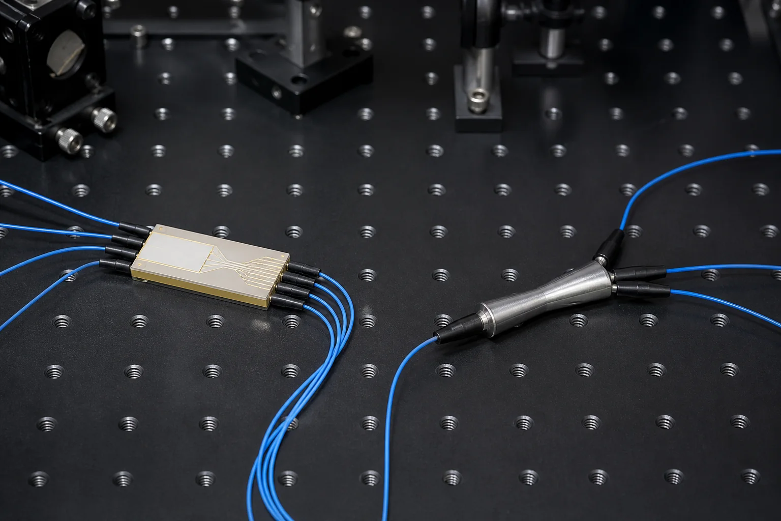
Definitions: PLC and FBT Splitters
Before diving into the comparison, it is essential to understand what each splitter is and how it works.
What is a PLC Splitter?
A PLC splitter is a micro-optical component fabricated using planar lightwave circuit technology. It consists of a silica glass chip with a network of optical waveguides that split an input signal into multiple output signals with precise ratios. PLC splitters are manufactured using semiconductor lithography, which allows for high precision and repeatability. They are available in standard split ratios such as 1×2, 1×4, 1×8, 1×16, 1×32, and 1×64, as well as 2xN configurations.
What is an FBT Splitter?
An FBT splitter is made by fusing and tapering two or more optical fibers together. During manufacturing, the fibers are heated and stretched so that the optical coupling region is created. FBT splitters are typically used for low split counts (1×2, 1×4, and sometimes 1×8) and are known for their low cost and simplicity. The splitting ratio is controlled by the length and taper profile of the fused region.
Performance Comparison: Insertion Loss and Uniformity
One of the most significant differences between PLC and FBT splitters is their optical performance, particularly insertion loss and uniformity.
Insertion Loss
Insertion loss is the total optical power lost through the splitter. For a 1xN splitter, the theoretical minimum loss is 10 log(N) dB. For example, a 1×8 splitter has a theoretical loss of about 9.03 dB. In practice, both PLC and FBT splitters add excess loss. PLC splitters typically have lower excess loss, especially for higher split ratios. For a 1×8 splitter, a typical PLC splitter might have an insertion loss of 10.2 dB, while an FBT splitter might be around 10.5 dB. For 1×16 and above, PLC splitters are far superior; FBT splitters become impractical due to high loss and poor uniformity.
Uniformity
Uniformity refers to the maximum difference in insertion loss among the output ports. PLC splitters excel in this area, with uniformity typically within 0.5 dB for 1×8 and 1.0 dB for 1×32. FBT splitters, on the other hand, often have uniformity of 1.0 dB or worse, even for low split ratios. Poor uniformity means that some subscribers receive a weaker signal, which can limit the reach and data rate of the PON.
| Parameter | PLC Splitter (1×8) | FBT Splitter (1×8) |
|---|---|---|
| Insertion loss (typical) | 10.2 dB | 10.5 dB |
| Uniformity (max) | 0.5 dB | 1.0 dB |
| Wavelength range | 1260–1650 nm | 1310/1490/1550 nm (narrow) |
| Split ratio availability | 1×2 to 1×64 | 1×2, 1×4, sometimes 1×8 |
| Cost per port (for 1×8) | Higher | Lower |
Wavelength Dependence and Operating Range
Another crucial factor is the wavelength range over which the splitter operates.
PLC Splitters: Broadband Operation
PLC splitters are inherently broadband, operating across the entire telecommunications wavelength range from 1260 nm to 1650 nm. This makes them ideal for triple-play services (data, voice, video) that use different wavelengths, such as 1310 nm for upstream, 1490 nm for downstream, and 1550 nm for video overlay. They also support future wavelength upgrades, such as 100G PON and beyond.
FBT Splitters: Narrowband Limitation
FBT splitters are wavelength-dependent because the coupling ratio varies with wavelength. They are typically optimized for a specific wavelength, such as 1310 nm or 1550 nm. If you need to split multiple wavelengths simultaneously, you would need separate FBT splitters for each wavelength, or you would accept performance degradation. This limitation makes FBT splitters unsuitable for modern PON systems that rely on wavelength-division multiplexing.
Cost Analysis: Initial Price vs. Total Cost of Ownership
Cost is often the primary driver in component selection, but it is important to consider the total cost of ownership, not just the purchase price.
Initial Purchase Price
FBT splitters are generally cheaper than PLC splitters for low split ratios (1×2, 1×4). The manufacturing process is simpler and less capital-intensive. For a 1×8 splitter, the price difference may be 20–30% in favor of FBT. However, as split ratio increases, the cost of FBT splitters rises sharply, and they become more expensive than PLC splitters for 1×16 and above, if they are even available.
Total Cost of Ownership
The lower initial cost of FBT splitters can be offset by higher operational expenses. Poor uniformity may require more powerful optical transceivers or shorter reach, increasing network deployment costs. The lack of wavelength flexibility may necessitate additional splitters for multi-wavelength services. PLC splitters, with their superior performance and reliability, reduce these hidden costs. For a typical PON deployment, PLC splitters offer a lower total cost of ownership.
Reliability and Environmental Stability
Network reliability is paramount, and the splitter’s ability to withstand environmental stress directly affects uptime.
PLC Splitters: High Reliability
PLC splitters are fabricated on a silica glass chip, which is inherently stable and resistant to temperature variations, humidity, and mechanical shock. They are qualified to meet stringent Telcordia GR-1221 standards for reliability. The waveguide structure is less prone to degradation over time, ensuring consistent performance for 20+ years.
FBT Splitters: More Susceptible to Environmental Factors
FBT splitters are made by fusing fibers, which creates a stress point that can be sensitive to temperature changes and mechanical strain. The fused taper region is fragile and requires careful packaging. While modern FBT splitters are protected in steel tubes or other housings, they are still more vulnerable to environmental stress than PLC splitters. In outdoor or harsh environments, PLC splitters are the safer choice.
Installation and Form Factor Considerations
The physical size and packaging of the splitter affect installation, especially in space-constrained closures.
Compactness of PLC Splitters
PLC splitters are extremely compact, especially for high split ratios. A 1×32 PLC splitter can fit in a small package, making it ideal for high-density applications like fiber distribution hubs and optical network terminals (ONTs). They are available in various form factors, including bare fiber, blockless, and cassette types, which facilitate easy integration.
Bulkiness of FBT Splitters
FBT splitters are bulkier because they consist of multiple fused fiber sections. For high split ratios, the physical size increases significantly, making them difficult to manage in small enclosures. This can lead to increased installation time and potential fiber bending issues. For low split counts (1×2, 1×4), the size difference is negligible.
Testing and Quality Assurance
Regardless of the splitter type, proper testing is essential to ensure it meets specifications. The Fiber Optic Association provides a comprehensive guide to testing fiber optic components, which is a useful reference for understanding test methods.
Key Parameters to Test
- Insertion loss: measure at all operating wavelengths.
- Return loss: ensure it meets the required minimum (typically >50 dB for PLC, >40 dB for FBT).
- Directivity: the isolation between input ports (for 2xN splitters).
- Polarization dependent loss (PDL): should be low, especially for PLC splitters.
Quality Standards
Quality splitters should comply with international standards such as the ITU-T G.657 recommendations for bend-insensitive fibers, which are often used in splitter pigtails. Additionally, IEC 61753-1 covers performance standards for passive optical components. When procuring splitters, ask for test reports that show compliance with these standards.
Common Mistakes to Avoid
Engineers and procurement teams often make avoidable errors when choosing splitters. Here are the most common pitfalls:
- Choosing FBT for high split ratios: FBT splitters beyond 1×8 are not recommended due to high loss and poor uniformity.
- Ignoring wavelength range: Using an FBT splitter designed for 1310 nm in a system that also uses 1550 nm will cause excessive loss at 1550 nm.
- Overlooking uniformity: In a PON, a large uniformity difference means some subscribers get a weak signal, leading to service issues.
- Not considering future upgrades: If you plan to upgrade to 10G PON or beyond, you need splitters that support the full wavelength range—PLC is the safe bet.
- Cheaping out on quality: Low-cost splitters may fail prematurely or not meet specifications, causing network downtime and expensive troubleshooting.
Procurement Checklist
Use this checklist when evaluating splitter suppliers:
- Confirm the split ratio and configuration (1xN or 2xN).
- Verify insertion loss and uniformity at all required wavelengths.
- Check the operating temperature range (-40°C to +85°C is typical).
- Ensure the splitter meets relevant ITU-T and IEC standards.
- Request test reports from a reputable test house.
- Evaluate the packaging and form factor for your installation environment.
- Consider the supplier’s manufacturing capabilities and quality control processes.
- Ask about warranty and after-sales support.
Practical Recommendations
Based on the performance, cost, and reliability analysis, here are clear recommendations:
When to Choose PLC Splitters
- For any PON deployment (GPON, EPON, XGS-PON, NG-PON2).
- When you need split ratios of 1×8 or higher.
- When you require broadband operation for multiple wavelengths.
- When network reliability and long-term stability are critical.
- When space is limited and compact packaging is needed.
When FBT Splitters Might Be Acceptable
- For low split ratios (1×2, 1×4) in short-reach, single-wavelength applications.
- In cost-sensitive deployments where performance requirements are minimal.
- For temporary or test setups where low cost is more important than long-term reliability.
Conclusion
The PLC splitter vs FBT splitter decision is straightforward for most modern networks: PLC splitters are the recommended choice for PON and other high-performance fiber optic systems. They offer superior uniformity, broadband operation, and reliability, which outweigh their slightly higher upfront cost. FBT splitters remain a niche option for low-count, cost-constrained applications. If you are planning a new network or upgrading an existing one, choose PLC splitters to ensure scalability and performance. For more information on our PLC splitter products, visit our PLC splitter product page. To learn about our quality assurance processes, check our quality page. If you need assistance selecting the right splitter, contact our team.
Frequently Asked Questions
What is the main difference between PLC and FBT splitters?
PLC splitters use planar waveguide technology, offering better uniformity, broadband wavelength support, and compact size, while FBT splitters are fused fiber devices that are cheaper but have limited split ratios and wavelength dependence.
Can FBT splitters be used for GPON?
FBT splitters can be used for low split ratios (1×2, 1×4) in GPON, but they are not recommended for higher splits or future upgrades due to poor uniformity and wavelength limitations. PLC splitters are preferred for GPON.
Are PLC splitters more expensive than FBT splitters?
For low split ratios like 1×2 and 1×4, FBT splitters are generally cheaper. However, for 1×8 and above, the cost difference narrows, and PLC splitters become more cost-effective when considering total cost of ownership.
What is the typical insertion loss for a 1×8 PLC splitter?
A typical 1×8 PLC splitter has an insertion loss of about 10.2 dB, including excess loss. The theoretical minimum is 9.03 dB.
Can FBT splitters handle multiple wavelengths?
FBT splitters are wavelength-dependent and are usually optimized for a single wavelength, such as 1310 nm or 1550 nm. They are not suitable for WDM systems that require simultaneous transmission of multiple wavelengths.
What are the common split ratios available for PLC splitters?
PLC splitters are available in standard ratios from 1×2 to 1×64, including 1×8, 1×16, 1×32, and 2xN configurations.
Complete topic guide: PLC Fiber Splitters: Complete Design and Selection Guide.







