
High fiber insertion loss is the silent killer of optical network performance. In short, it is the reduction in optical power as light travels through a fiber link, and when it exceeds the system’s power budget, it causes bit errors, retransmissions, and even complete link failure. The causes range from poor connector hygiene to improper splicing, and most are preventable with correct procedures and regular inspection. This guide explains the 12 most common causes and how to fix them, so you can keep your links running at peak efficiency.
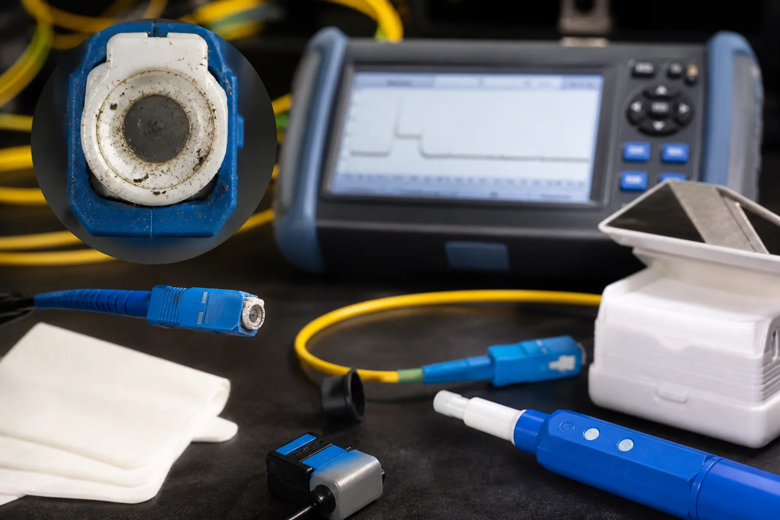
What Exactly Is Insertion Loss?
Insertion loss (IL) is the total optical power loss introduced by a component (such as a connector, splice, or coupler) when inserted into a fiber link. It is expressed in decibels (dB) and is always a positive value for passive components. The lower the dB value, the better the performance.
How It Differs from Return Loss and Attenuation
Insertion loss is often confused with return loss and attenuation, but they measure different phenomena:
- Insertion loss – the forward power lost as light passes through a component.
- Return loss – the backward reflection of light toward the source, also measured in dB but higher values are better.
- Attenuation – the natural loss of signal strength over distance in the fiber itself, typically specified per kilometer.
In practice, insertion loss includes both the intrinsic loss of the component and any additional loss due to misalignment, contamination, or other defects.
Why Understanding Insertion Loss Matters
Knowing the causes of high fiber insertion loss is critical for network designers, installers, and maintenance teams. A link that looks fine on paper may fail in the field if the actual insertion loss exceeds the system’s power budget. This is especially important in:
- Data centers – where high-density cabling and frequent patching increase the risk of contamination and damage.
- Telecom networks – where long spans and multiple splices can accumulate loss.
- FTTH deployments – where every dB counts to meet service level agreements.
By identifying the root cause of high loss, you can avoid costly troubleshooting, downtime, and premature component replacement.
Core Technical Differences That Affect Loss
Several physical and environmental factors influence insertion loss. Understanding these differences helps you diagnose problems and choose the right components.
Single-Mode vs. Multimode Fiber
Single-mode fiber (SMF) has a small core (about 9 µm) and supports only one propagation mode, while multimode fiber (MMF) has a larger core (50 or 62.5 µm) and supports many modes. Insertion loss specifications differ: typical connector loss for SMF is around 0.3 dB, while for MMF it can be slightly higher due to modal effects. However, the fundamental causes of loss—contamination, misalignment, and poor polishing—are the same.
Connector Types and Polish
Connector types (e.g., SC, LC, ST) and polish styles (PC, UPC, APC) affect how well fiber ends mate. APC (angled physical contact) connectors have an 8° angle that reduces back reflection, but they must be matched with other APC connectors; mixing APC with UPC or PC can cause high loss and damage. The quality of the ferrule and the cleanliness of the end face are also critical.
Splicing: Fusion vs. Mechanical
Fusion splicing uses an electric arc to melt and join fiber ends, producing very low loss (typically 0.02–0.05 dB). Mechanical splicing aligns fibers with a sleeve and index-matching gel, resulting in higher loss (typically 0.2–0.5 dB). The choice affects link loss, especially in long-haul networks where many splices are used.
Wavelength Dependence
Insertion loss can vary with wavelength. For example, a connector that performs well at 1310 nm may show slightly different loss at 1550 nm due to mode field diameter changes. This is why loss measurements are often specified at a particular wavelength, and why testing at the operating wavelength is recommended.
In the following sections, we will dive into the 12 specific causes of high insertion loss, starting with the most common: contamination.
Comparing the Main Causes of High Fiber Insertion Loss
When you suspect that high fiber insertion loss is degrading your link, the first step is to identify which factor is responsible. The table below summarizes the most common causes, their typical magnitude, and how they are usually diagnosed. The values shown are typical engineering ranges, not normative limits; always refer to the relevant standard (e.g., IEC 61753, TIA-568) for your specific application.
| Cause | Typical Loss (dB) | Diagnostic Method | Fix |
|---|---|---|---|
| Dirty connector endface | 0.5 – 2.0 | Visual inspection (video scope) | Clean with proper ferrule cleaner |
| Poor connector mating (air gap, misalignment) | 0.2 – 1.0 | OTDR trace, insertion loss test | Re-terminate or replace connector |
| Fiber bend (macrobend) | 0.1 – 0.5 per bend (tight bend) | Visual inspection, OTDR (bend loss event) | Relieve bend radius, use bend-insensitive fiber |
| Fiber splice (fusion or mechanical) | 0.05 – 0.3 (fusion), 0.2 – 0.5 (mechanical) | OTDR splice loss measurement | Re-splice or optimize splice parameters |
| Mismatched fiber types (e.g., 50/125 vs 62.5/125) | 1.0 – 3.0 (at multimode interface) | Check fiber type labels, OTDR | Use mode-conditioning patchcord or replace fiber |
| Wavelength-dependent attenuation (e.g., water peak) | 0.1 – 0.3 (at 1383 nm) | OTDR at multiple wavelengths | Choose fiber with low water peak (e.g., G.652.D) |
Decision Criteria: How to Choose the Right Fix
Not every cause requires the same response. Use the following criteria to decide where to focus your troubleshooting:
- Magnitude of loss: If the loss is above 1 dB at a single connection, contamination or a poor physical contact is likely. If it is below 0.5 dB, look for bend or splice issues.
- Location of loss: An OTDR trace will show whether the loss is at a connector, splice, or distributed along the fiber. A sharp event indicates a connector or bend; a gradual slope suggests attenuation.
- Wavelength behavior: If loss increases at longer wavelengths (e.g., 1550 nm vs 1310 nm), macrobending is probable. If loss is high only at 1383 nm, water peak is the culprit.
- Budget headroom: If your link has plenty of margin, you might tolerate a slightly high splice loss. If you are near the limit, every tenth of a dB matters.
Prioritizing the Most Common Culprits
In practice, dirty connectors account for the majority of high insertion loss issues. Therefore, start with cleaning and inspection before re-terminating or re-splicing. Only if cleaning does not resolve the problem should you move to more invasive fixes.
Worked Example: Diagnosing a 2.5 dB Loss
Suppose you have a 200 m single-mode link with two connector pairs and one fusion splice. The expected loss is roughly 0.5 dB (0.3 dB for connectors + 0.2 dB for splice). Your OTDR shows a total loss of 2.5 dB, so you have about 2 dB of excess loss.
Step 1: Inspect the connectors. Using a video scope, you find a dust particle on the far-end connector. You clean it and re-test. The loss drops to 1.8 dB – improvement, but still high.
Step 2: Examine the OTDR trace. The trace shows a small step at the splice location, indicating about 0.5 dB splice loss, which is higher than typical. You also notice a slight slope over the last 50 m, suggesting a macrobend near the termination panel.
Step 3: Check the bend. You find a tight bend where the cable is routed around a corner. After relieving the bend radius, the loss falls to 0.6 dB – acceptable for this link.
Step 4: Decision. The splice loss of 0.5 dB is within typical fusion splice values (0.05–0.3 dB) but on the high side. Since your link budget has 1 dB margin, you decide to leave the splice as is, but you note it for future monitoring.
Selection Guidance: What to Do When Multiple Causes Coexist
When you have multiple potential causes, address them in order of cost and disruption. Cleaning is cheap and non-invasive; re-termination is more expensive; re-splicing may require a splice machine and access to the cable. Use the following guidance:
- If the loss is at a connector: Clean first. If the loss persists, inspect for scratches or pits – if present, re-terminate.
- If the loss is at a splice: Try re-splicing once. If the loss remains high, check for fiber mismatch or contamination in the splice holder.
- If the loss is distributed: Look for bends, kinks, or damage. Replace the cable section if necessary.
Remember that standards like TIA-568 set maximum insertion loss for permanent links (e.g., 0.75 dB for a connector pair in some cases), but your actual system budget may be tighter. Always design with margin for aging and future maintenance.
Installation and Testing Pitfalls That Drive Up Loss
Even when components are correctly specified, poor installation practice remains one of the most frequent causes of high fiber insertion loss. The physical layer is unforgiving: a single dust particle, a slight misalignment, or an overtightened connector can push loss far beyond acceptable limits.
Common Mistakes During Cable Pulling and Termination
- Exceeding bend radius limits – During pulling, cables are often bent around sharp corners or under tension. This creates micro-bends that scatter light and increase loss. Always respect the manufacturer’s minimum bend radius, which is typically 10 times the cable diameter for standard single-mode fiber, but can be as low as 5 mm for bend-insensitive fibers.
- Dirty connectors – Touching the ferrule end-face with bare fingers, or leaving protective caps off during installation, invites contamination. Even a microscopic particle can cause significant back reflection and insertion loss. Always clean connectors before mating, and use a one-click cleaner or lint-free wipes with isopropyl alcohol.
- Improper cleave length – In fusion splicing, an incorrect cleave length leads to poor core alignment. The cleave angle should be within 0.5° for single-mode fiber; larger angles cause higher loss.
- Over-tightening connectors – Applying too much torque to a connector nut can distort the ferrule, especially in ceramic ferrules. Use a torque wrench if specified, and follow the manufacturer’s recommended tightening procedure.
Testing Errors That Mask or Inflate Loss Readings
Testing itself can introduce errors. A common mistake is using the wrong launch cable or not establishing a proper reference. For accurate insertion loss measurement, you must set the reference with the launch and receive cables connected directly, then insert the device under test. If you forget to clean the reference connectors, you’ll measure a higher loss than actual. Also, using a light source and power meter at the wrong wavelength (e.g., 1550 nm for a system designed for 1310 nm) will give misleading results because attenuation varies with wavelength.
Another pitfall is testing with a single reference jumper that has a damaged end-face. Always inspect the end-face with a scope before testing. And remember that an OTDR (optical time-domain reflectometer) measures loss differently than a light source and power meter; OTDRs can overestimate loss at connectors due to the “gainers” effect. For final acceptance, use a light source and power meter for end-to-end loss measurement.
Buyer Checklist: What to Look For to Avoid High Insertion Loss
When purchasing fiber optic components or contracting installation, use this checklist to reduce the risk of high insertion loss.
Component Selection
- Connector polish type – For single-mode, use UPC or APC. APC (angle-polished) is preferred for high-power or RFoG applications; UPC is common for standard telecom. Ensure the polish matches the system design.
- Ferrule quality – Look for zirconia ceramic ferrules with a smooth, scratch-free end-face. The radius of curvature and apex offset should meet IEC 61753-1 standards, but typical values are 8–10 mm radius and apex offset less than 50 µm.
- Cable type – For tight bends, choose bend-insensitive fiber (e.g., ITU-T G.657) which has a reduced bend radius specification. This is especially important in data centers or FTTH installations.
- Pre-terminated assemblies – Factory-terminated pigtails and patch cords often have lower loss than field-terminated ones because they are polished and tested under controlled conditions. If you must field-terminate, use a reliable kit and test every connection.
Installation and Verification
- Contractor qualifications – Ensure the installer is certified and experienced. Ask for references and proof of training.
- Test plan – Require a documented test plan that includes insertion loss measurements on every fiber, using a light source and power meter at the operating wavelength. The acceptable loss limit should be based on the system budget, not just a generic value.
- Documentation – Insist on as-built documentation that includes test results, connector types, and splice locations. This helps future troubleshooting.
Practical Recommendation
To minimize the causes of high fiber insertion loss, adopt a three-pronged approach: specify correctly, install carefully, and verify thoroughly. Use high-quality components that meet or exceed industry standards, train your installers, and never skip the final loss test. If you are designing a link, calculate the total loss budget using typical values for connectors (0.3–0.5 dB per mated pair for single-mode) and splices (0.1–0.2 dB per fusion splice), and then add margin for aging and environmental factors.
Conclusion: Control the Process, Control the Loss
High fiber insertion loss is rarely caused by a single dramatic event; it is usually the accumulation of small oversights. By understanding the installation and testing pitfalls, and by using a disciplined buyer checklist, you can keep the causes of high fiber insertion loss at bay. Remember that standards define the minimum performance, but your engineering judgment should aim for better. Always measure, always document, and always clean. In the end, a few minutes of extra care during installation can save hours of troubleshooting later.
Frequently Asked Questions
What are the most common causes of high fiber insertion loss?
Common causes include poor connector end-face contamination, improper connector mating, fiber misalignment, excessive bending, and using mismatched fiber types. Additionally, splices with high loss, damaged fiber, and incorrect cleaning methods contribute. Identifying the specific cause requires an OTDR and visual inspection.
How does connector contamination affect insertion loss and how can I prevent it?
Contamination, such as dust or oil, on connector end-faces causes scattering and absorption, increasing insertion loss. Prevent it by always using dust caps, cleaning connectors with appropriate tools (e.g., dry cleaning or one-click cleaners) before mating, and inspecting with a scope. Never touch end-faces and ensure connectors are clean before testing.
Can mismatched fiber types cause high insertion loss?
Yes, mismatched fiber types, such as connecting single-mode to multimode fiber, cause high loss due to core size and numerical aperture differences. Even within single-mode, mismatched mode-field diameters can increase loss. Always ensure fiber types are compatible, and use hybrid patch cords or mode-conditioning cables if necessary.
What is the impact of poor splicing on insertion loss and how can I minimize it?
Poor splicing, whether fusion or mechanical, can introduce high loss due to misalignment, air gaps, or contamination. To minimize loss, use a fusion splicer with proper alignment, clean fiber ends, and ensure the splice is protected. For mechanical splices, use index-matching gel and follow manufacturer instructions. Test splices with an OTDR to verify low loss.
How does excessive bending affect insertion loss and what bend radius should I maintain?
Excessive bending causes light to leak from the core, increasing insertion loss. Maintain a bend radius larger than the manufacturer's minimum, typically 10 times the cable diameter for static bends and 20 times for dynamic. For patch cords, avoid tight loops. Use bend-insensitive fiber if tight bends are unavoidable.
What testing methods can identify the source of high insertion loss?
Use an optical loss test set (OLTS) to measure total link loss and an OTDR to locate loss events like connectors, splices, and bends. Visual inspection with a microscope identifies contamination or damage. Perform cleaning and retesting to isolate issues. For precise measurement, ensure test reference cords are clean and calibrated.
Complete topic guide: Fiber Optic Troubleshooting and Maintenance Guide.







