
Introduction: A Milestone for Community Connectivity
When Ann Arbor and Ypsilanti were linked by an 18-mile fiber optic network, it wasn’t just a local infrastructure win—it was a practical case study in metro fiber engineering. The project, reported by MLive, demonstrates how fiber optics can connect communities, support economic growth, and provide high-speed internet for residents and businesses. But behind the ribbon-cutting lies a complex design and deployment process that offers valuable lessons for network engineers, contractors, and procurement specialists.
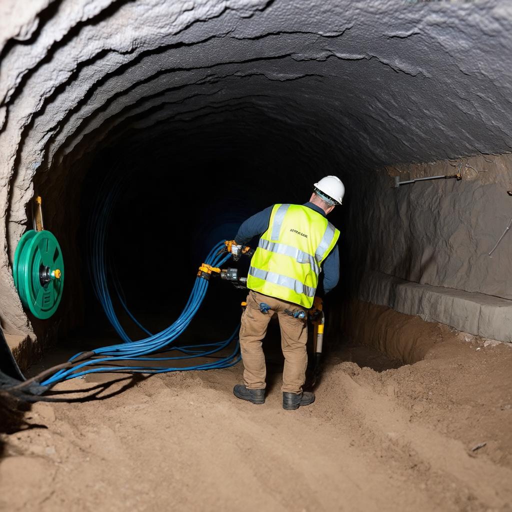
In this article, we break down the engineering decisions that make such a network successful: choosing the right fiber, calculating loss budgets, testing splices, and selecting components that stand the test of time. Whether you’re planning a similar municipal network or simply upgrading an enterprise campus, understanding these principles will help you make informed choices—and avoid costly mistakes.
The Anatomy of a Metro Fiber Network
An 18-mile route is considered a metro or regional network, typically spanning multiple neighborhoods, business districts, and possibly rural stretches. Such networks often use a ring topology to provide redundancy. If one fiber is cut, traffic can be rerouted in the opposite direction. This is a fundamental design consideration.
Fiber Type: SMF-28e+ or G.652.D?
For distances of 18 miles (about 29 km), single-mode fiber is the only logical choice. Multimode fiber is limited to a few hundred meters, especially at high data rates. Within single-mode, the most common specification is ITU-T G.652.D, which offers low water peak and is compatible with both 1310 nm and 1550 nm transmission windows. For metro networks, G.652.D is the workhorse.
However, if the route includes tight bends—for example, in underground ducts or building risers—engineers may choose G.657.A1 or A2 fiber, which has a smaller minimum bend radius. This is a key selection criterion. In our fiber optic cable range, we offer both types.
Cable Construction: Outdoor vs. Indoor
For an intercity link, outdoor cable is required. Loose-tube cable, with gel-filled buffer tubes, is standard for direct burial or duct installation. It protects fibers from moisture and mechanical stress. If the route includes aerial sections, an ADSS or OPGW cable might be used. The choice depends on the environment and installation method.
For transitions into buildings, a breakout cable or indoor-rated cable is used. Proper transition points and patch panels are essential for maintaining performance.
Optical Power Budget: The Core Engineering Calculation
Before any fiber is laid, the network designer must calculate the optical power budget. This ensures that the signal arriving at the receiver is strong enough for reliable operation, even after all connector and splice losses.
For an 18-mile link, the total distance is approximately 29 km. Let’s assume we use a standard single-mode fiber with a typical attenuation of 0.4 dB/km at 1310 nm and 0.25 dB/km at 1550 nm. The link will have several splices (fusion splices) and connectors.
Worked Example: Loss Budget for an 18-Mile Link
Let’s calculate the worst-case loss for a 29 km link using 1550 nm, assuming:
- Fiber attenuation: 0.25 dB/km
- Number of fusion splices: 12 (every ~2.4 km), each with 0.1 dB loss
- Number of connector pairs: 4 (at each end and intermediate patch panels), each with 0.5 dB loss
- System margin: 3 dB
Total fiber loss = 29 km × 0.25 dB/km = 7.25 dB
Total splice loss = 12 × 0.1 dB = 1.2 dB
Total connector loss = 4 × 0.5 dB = 2.0 dB
Total link loss = 7.25 + 1.2 + 2.0 = 10.45 dB
Adding system margin (3 dB), the required power budget is 13.45 dB.
The 24 dB limit previously attributed to 10GBASE-ER was incorrect. IEEE 802.3 discussion of Table 52-24 identifies an 11 dB maximum channel insertion loss for 10GBASE-ER. This example has 10.45 dB estimated channel loss before the separate 3 dB design allowance: only 0.55 dB remains below 11 dB. It therefore does not meet the stated 3 dB allowance and cannot be declared comfortably within budget. Reduce loss or select qualified optics after checking the complete module specification.
This calculation underscores the importance of specifying low-loss connectors and splices. Using high-quality components, such as fiber optic adapters and patch cords, directly affects the loss budget.
Splicing and Testing: Ensuring Quality
Once the cable is installed, splicing and testing are critical. Fusion splicing is the preferred method for outdoor single-mode fiber because it offers the lowest loss and highest reliability. Each splice should be tested with an OTDR (Optical Time-Domain Reflectometer) to verify loss and identify any issues.
OTDR Testing: What to Look For
An OTDR sends light pulses down the fiber and analyzes the backscattered light to measure loss and locate faults. For a metro link, the OTDR trace should show a gradual slope (attenuation), with small dips at splice points and larger drops at connectors. Any sudden event could indicate a bend, break, or poor splice.
Typical acceptance criteria for a metro network are:
- Fiber attenuation less than 0.25 dB/km at 1550 nm
- Splice loss less than 0.1 dB
- Connector loss less than 0.5 dB
- ORL (Optical Return Loss) greater than 30 dB for connectors
If you need to perform these tests, our fiber tools category includes OTDRs and power meters.
Standards Compliance
Ensuring that the installed network meets international standards is non-negotiable. The key standards are:
- ITU-T G.652 – Fiber characteristics
- IEC 60794 – Optical fibre cables
- FOA standards – Installation and testing
These standards define performance requirements, test methods, and installation practices. By specifying compliant components, you ensure interoperability and longevity.
Economic and Strategic Benefits of Community Fiber
The Ann Arbor–Ypsilanti link is part of a broader trend of municipalities investing in fiber infrastructure to attract businesses, support remote work, and bridge the digital divide. For network engineers, this means more opportunities to design and deploy fiber. For procurement specialists, it highlights the importance of sourcing quality materials at scale.
When planning such a network, consider not only the initial build cost but also the lifecycle cost. Using high-quality fiber and components from a reliable manufacturer, such as fiber optic products wholesale, can reduce maintenance and future upgrade costs.
Conclusion: Lessons for Your Next Project
The 18-mile fiber link between Ann Arbor and Ypsilanti is more than a news story; it’s a blueprint for successful fiber deployment. By paying attention to fiber selection, loss budgets, splicing, and testing, you can ensure your network performs reliably for decades.
As a manufacturer, we at Liqiba are committed to providing high-quality fiber optic products that meet international standards. Whether you’re working on a municipal network, a data center, or a campus, our team can help you choose the right components. Explore our products to see how we can support your project.
If you have specific questions about your network design, don’t hesitate to contact us. We’re here to help you build a future-proof fiber network.
Frequently Asked Questions
Does the 29 km example pass a 10GBASE-ER budget with 3 dB reserve?
No. Its estimated channel loss is 10.45 dB; an 11 dB channel limit leaves 0.55 dB, short of the stated 3 dB design allowance. Recalculate with the selected module specifications and measured link losses before acceptance.
What evidence should accompany acceptance of this metro route?
Record route length, fiber and connector identities, bidirectional splice-event results where appropriate, and end-to-end insertion loss at the operating wavelength. Compare these measurements with the chosen optics and the project restoration allowance.
Related: Fiber Macrobend vs Microbend Loss: Diagnosis and Prevention







