
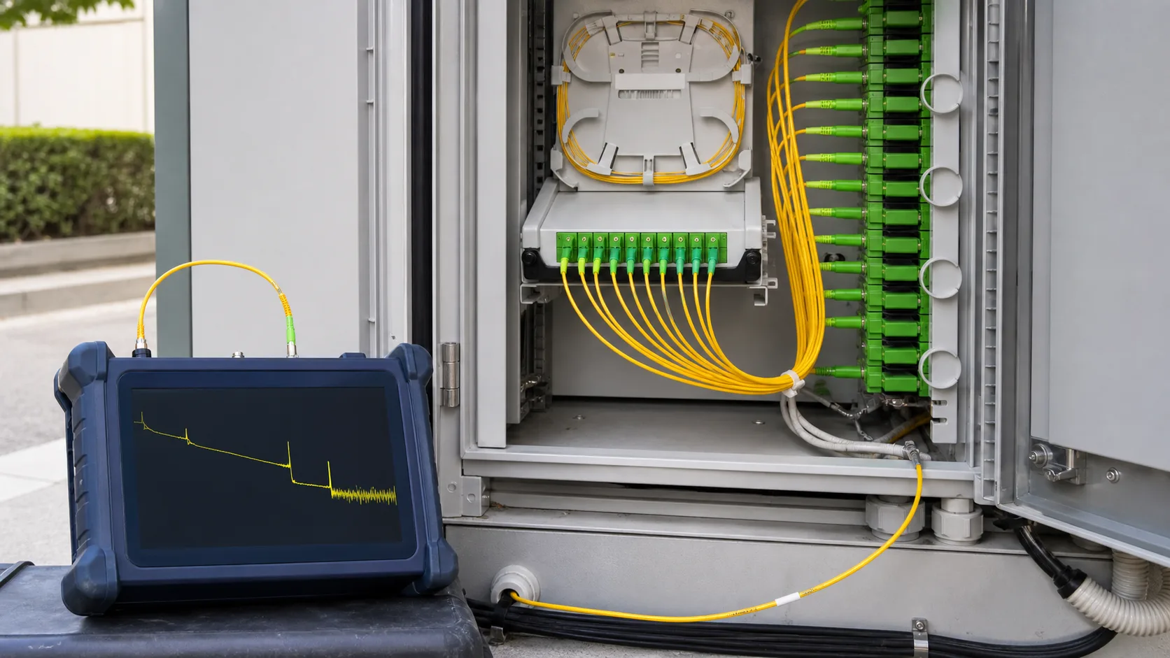
Executive summary: The clearest way to OTDR-test one branch of a 1:32 PON is usually from the subscriber side toward the splitter and OLT. Start with a short pulse to resolve the drop segment, then use a longer acquisition to see through the splitter. Treat downstream traces cautiously because backscatter from 32 branches is combined. OTDR results should complement—not replace—end-to-end insertion-loss testing.
A 1:32 passive optical splitter is easy to represent on a network diagram and difficult to interpret on an OTDR. Its splitting loss consumes much of the instrument’s dynamic range, while the point-to-multipoint topology overlays downstream branch responses. A procedure that works on a point-to-point cable can therefore create a convincing but incomplete PON trace.
First decide what the test must prove
Commissioning, acceptance, troubleshooting and maintenance are different jobs. Commissioning may require continuity, polarity, end-to-end loss and a baseline trace for every branch. Troubleshooting asks where a new loss, reflection or break is located. In-service monitoring may use a filtered maintenance wavelength and must avoid disrupting traffic.
Write the test objective before connecting the instrument. If the objective is “prove the complete ODN stays inside the optical power budget,” use an optical loss test set or PON power meter with the approved wavelengths and references. If the objective is “locate a bend between the customer terminal and splitter,” an OTDR is the appropriate diagnostic tool.
For instrument selection and launch accessories, see the commercial fiber tools and test equipment page. The final choice must match network wavelength, split loss, connector type, required dead zones and live-network safety.
Why downstream and upstream traces look different
From the OLT or splitter-input side, an OTDR pulse enters all 32 output branches. The instrument receives the sum of their backscatter. It may show the splitter as one large event and several branch ends, but an event after the splitter can be difficult or impossible to assign to a specific customer branch.
From one subscriber output toward the OLT, the OTDR first sees one drop fiber. It then sees the large splitter loss and continues on the common feeder if enough dynamic range remains. The Fiber Optic Association’s FTTH testing reference explains that upstream testing is generally easier because only one branch is represented before the splitter.
| Test direction | What it shows well | Main limitation |
|---|---|---|
| OLT toward splitter and branches | Feeder section, splitter location, branch continuity and differing end distances | Backscatter from branches is combined; a branch fault may not be uniquely identified. |
| Subscriber toward splitter and OLT | Individual drop events, drop length, splitter event and common feeder when range permits | Requires access to each branch and safe isolation or an approved live-PON method. |
| Both directions | More complete event characterization and comparison | More time, access coordination and disciplined file naming are required. |
Safety and network-state checks
Determine whether the PON is dark, under construction or carrying service. Never assume an unused-looking port is dark. Identify OLT and ONT wavelengths, optical power, connector polish and the operator’s isolation procedure. Inspect and clean the test connector before mating; APC and UPC connectors must not be mixed.
For a live PON, use only a purpose-designed filtered OTDR at the approved maintenance wavelength. VIAVI’s current OTDR selection guidance distinguishes 1310/1550 nm installation tests from filtered 1625/1650 nm in-service troubleshooting. ITU-T L.301, formerly L.41, assigns maintenance-wavelength concepts for fibers carrying signals. The actual network plan and equipment limits take precedence.
If the procedure requires disconnecting an active OLT or ONT, obtain authorization and confirm the outage boundary. Protect open connectors immediately. A troubleshooting action that contaminates 32 ports can create more faults than it finds.
Use launch and receive fibers correctly
A launch fiber lets the OTDR recover from its initial dead zone before the first connector under test. A receive fiber helps characterize the far-end connector when the route and topology allow it. Both should match fiber type and connector polish, be clean, and be long enough for the selected OTDR pulse without becoming an unnecessary handling burden.
Do not reuse a launch-cable length from another project without checking pulse width, event dead zone and route geometry. The detailed OTDR launch cable length guide explains how instrument settings and first-event requirements affect the choice.
Two-stage pulse strategy for a 1:32 splitter
No single pulse width is ideal. A short pulse provides better spatial resolution but less energy. A long pulse improves dynamic range through the splitter but increases dead zones and can hide nearby events. A practical method records at least two acquisitions.
| Stage | Example pulse range | Purpose | Caution |
|---|---|---|---|
| High-resolution branch trace | 5, 10 or 30 ns | Resolve connectors, splices and bends from the subscriber toward the splitter. | The trace may end at or shortly after the high-loss splitter. |
| Through-splitter trace | 100 to 500 ns | Validate cumulative loss toward the OLT and look for feeder problems. | Larger dead zones can merge close events; compare with the short-pulse trace. |
These ranges come from an EXFO PON troubleshooting application note. They are examples, not universal settings. Instrument output power, dynamic range, averaging, fiber length, splitter loss and noise determine the final setup. Begin with the instrument’s PON mode when available, save the automatic result, then confirm critical events manually.
Set range, index and averaging deliberately
Set the distance range beyond the expected feeder end but not many times longer than necessary. An excessive range wastes acquisition points and can reduce useful resolution. Enter the cable’s group index or effective refractive index from the approved data; an incorrect value shifts event distances.
Increase averaging before jumping immediately to a very long pulse. More averages can improve signal-to-noise ratio while retaining better resolution, although test time increases. Stop averaging when the trace is stable enough for the decision; a visually smooth line is not automatically more accurate.
Use event thresholds appropriate to the acceptance plan. If thresholds are too high, small but important events disappear from the event table. If too low, noise becomes false events. Always inspect the trace around the splitter instead of relying only on automatic classification.
Interpret the splitter event without inventing precision
The splitter appears as a large nonreflective loss unless connector reflections are present around it. Its apparent OTDR loss can differ by direction because Rayleigh backscatter coefficients and mode-field differences influence one-way measurements. Bidirectional averaging is valuable for splice characterization, but a point-to-multipoint splitter topology makes ordinary two-end averaging more complex.
Do not subtract an assumed “theoretical” splitter loss and declare the rest of the network good. Compare against the actual splitter specification, connectorized assembly limits and approved ODN budget. The 1:32 splitter loss-budget example shows how splitter, fiber, connectors, splices and margin combine.
For component acceptance before installation, an optical source and power meter are usually clearer than an OTDR. The FOA’s splitter testing guide recommends measuring each output and explains why upstream and downstream procedures differ. See also optical power meter versus OTDR for the boundary between total-loss measurement and event location.
A field workflow that produces usable evidence
- Verify the design. Record OLT port, splitter ID and ratio, branch port, route length, wavelengths and approved loss budget.
- Confirm network state. Identify dark or live status and obtain the required isolation authorization.
- Inspect and clean. Check OTDR, launch lead and network connectors before every mating.
- Run a short-pulse upstream trace. Capture the subscriber drop and the events before the splitter.
- Run a longer-pulse acquisition. Attempt to see through the splitter and characterize the common feeder.
- Use the opposite direction when justified. Preserve the downstream trace as complementary evidence, not a branch-specific substitute.
- Measure end-to-end loss. Complete the OLTS or PON power test required by the acceptance plan.
- Save native files. Keep the instrument trace format plus a readable report and link both to the asset record.
Minimum trace record
| Record field | Why it matters |
|---|---|
| Instrument, serial and calibration status | Establishes measurement traceability. |
| Wavelength, pulse, range and averaging | Makes the trace reproducible and explains resolution. |
| Index of refraction and distance units | Supports accurate event-location comparison. |
| Launch/receive fiber identification | Explains near- and far-end connector visibility. |
| Direction and physical endpoints | Prevents upstream and downstream traces from being confused. |
| OLT, splitter and branch identifiers | Links the result to one service path. |
| Native trace and acceptance result | Preserves detail for future restoration and audit. |
Common mistakes
- Testing from the OLT side and assigning a combined event to one branch without evidence.
- Using one long pulse for the entire route and hiding close connectors in a dead zone.
- Connecting an unfiltered OTDR to a live PON.
- Mixing UPC and APC connectors or testing through contaminated end faces.
- Using OTDR event loss as a substitute for calibrated end-to-end insertion loss.
- Saving only a screenshot instead of the native trace and setup parameters.
Correct PON testing is a method, not a magic instrument mode. When direction, pulse strategy, network state and records are controlled, the OTDR becomes a powerful fault-location and baseline tool—even across a high-loss splitter.
Sources and verification note
This article was checked on August 31, 2026 against EXFO’s OTDR PON testing application note, current VIAVI OTDR selection guidance, the FOA FTTH and splitter testing references, and ITU-T maintenance-wavelength listings. Pulse values are source-based examples and must be adapted to the approved instrument and topology.
Frequently Asked Questions
Can a standard OTDR test through a 1:32 splitter?
It may, if it has sufficient dynamic range and suitable dead-zone performance, but the splitter creates a large loss and downstream branch overlap. A PON-optimized OTDR or multi-pulse analysis can be more reliable. Verify the instrument specification and test the actual topology.
Which direction is best for OTDR testing a PON?
Testing upstream from one subscriber branch usually gives the clearest view of that branch and the splitter event. A downstream trace from the OLT side combines backscatter from multiple branches and may not identify which branch contains a fault. Both directions can still provide useful, different evidence.
Which OTDR wavelength should be used on a live PON?
Use only an instrument and filtered maintenance wavelength approved for in-service testing, commonly 1625 nm or 1650 nm in supported systems. Do not connect an ordinary unfiltered OTDR to an active PON; follow the network operator and equipment manufacturer procedure.
Does an OTDR replace insertion-loss testing?
No. An OTDR locates and characterizes events, while an optical loss test set measures end-to-end channel loss against a reference. Acceptance plans often need both. A clean-looking trace does not by itself prove that total insertion loss meets the power budget.
Why use more than one pulse width on a splitter PON?
A short pulse improves resolution near closely spaced events but may not provide enough dynamic range through the splitter. A longer pulse reaches farther through high loss but enlarges dead zones. Multi-pulse testing combines complementary traces rather than forcing one setting to do everything.







