
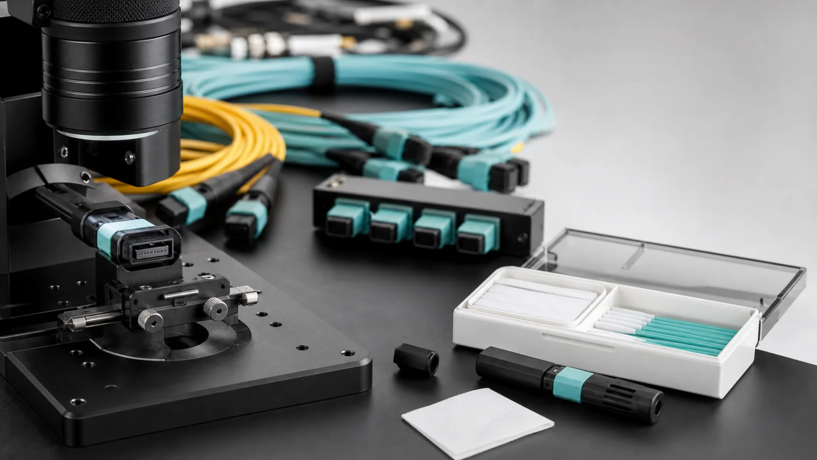
Executive summary: An MPO connector concentrates many optical paths on one rectangular ferrule, so one contaminated mating can affect several channels at once. A dependable acceptance process inspects the full ferrule, evaluates every fiber end face, cleans only with a qualified method, reinspects before mating, and records the result. This guide translates the engineering intent of IEC 61300-3-35:2022 into a practical workflow for teams defining MPO connector end-face inspection criteria.
The central rule is simple: inspect, clean if necessary, and inspect again. The implementation is less simple because an MPO interface is not merely a row of independent fibers. Particles on the ferrule can migrate during mating, guide-pin areas can retain debris, and a single inspection image must not be confused with proof of optical performance.
What IEC 61300-3-35:2022 actually establishes
IEC 61300-3-35:2022 covers observation and classification of debris, scratches and defects on fiber-optic connector end faces and fiber-stub transceivers. It specifies microscope requirements, an inspection procedure and quantitative image-analysis criteria. The third edition also emphasizes two points that matter to field acceptance.
First, visual inspection is additional evidence; it does not replace attenuation, return-loss or end-face-geometry measurements. Second, the contact area must be inspected for contamination. For rectangular ferrules, that means the whole ferrule surface, not only a small view around each fiber. The edition also removed the former Zone C and D inspection requirements and retained individual evaluation of the core and cladding regions.
The exact numerical limits vary by connector and fiber category. Use a licensed, current copy of the standard and the applicable project specification for formal pass/fail decisions. This article explains the workflow and record structure without presenting itself as a substitute for the standard.
Why MPO contamination has outsized consequences
A duplex connector affects one transmit and one receive path. A 12-, 16- or 24-fiber MPO can support multiple parallel lanes or several duplex channels. Dust, oil or cleaning residue can introduce insertion loss, reflectance or an air gap across more than one lane. When two ferrules are mated, debris can move or become embedded, contaminating both sides and turning one dirty connector into two maintenance problems.
High-density panels also make handling more difficult. Technicians may have limited access, trunk polarity must remain correct, and test reference cords may be connected many times. Inspection therefore belongs at receiving inspection, installation, commissioning and every subsequent remating—not only after a link fails.
Engineering module: a repeatable MPO acceptance workflow
| Step | Action | Evidence to retain |
|---|---|---|
| 1. Identify | Record cable ID, end, location, fiber count, keying and polarity method | Unique asset and port mapping |
| 2. Inspect ferrule | Use a compatible probe and a large field of view for the complete rectangular contact surface | Ferrule overview image |
| 3. Inspect fibers | Evaluate every end face with the correct analysis profile | Automated or controlled pass/fail record by fiber |
| 4. Clean | If contamination is removable, use a qualified MPO cleaning tool and controlled technique | Cleaning method and attempt number |
| 5. Reinspect | Never mate immediately after cleaning without another inspection | Final post-clean images |
| 6. Test link | Perform the specified insertion-loss, polarity and—when required—OTDR tests | Optical results tied to the same cable ID |
Step 1: control identity and polarity
Before opening a dust cap, confirm that the assembly matches the design: fiber count, male or female interface, key orientation, single-mode or multimode type and polarity method. Inspection cannot prevent a Method A, B or C polarity mismatch. Use the labeling and polarity records described in our MPO polarity guide, then preserve port identity throughout testing.
Step 2: inspect the complete rectangular ferrule
Select a probe tip and microscope intended for the exact MPO geometry. Fluke Networks’ standards guidance notes that IEC 61300-3-35 permits a large-field-of-view microscope of at least 6.4 × 2.5 mm for MPO ferrule inspection, with the ability to detect 10 µm debris. The purpose is to locate transferable particles across the contact surface before they migrate toward a fiber.
Inspect both the trunk and equipment sides. A factory dust cap is a handling control, not cleanliness evidence. Caps themselves can contain molded residue or collected particles, and repeatedly replacing a contaminated cap can recontaminate a cleaned ferrule.
Step 3: evaluate every fiber end face
After the ferrule overview, use the appropriate field of view and analysis profile for each fiber. IEC describes Zone A at the core and Zone B in the cladding. The 2022 edition states that only the portion of a defect that lies in the core is judged as being in the core; the remainder is treated as located in the cladding. Automated analysis improves consistency, but the microscope, probe tip, software profile and calibration must all be controlled.
Do not use a generic single-fiber profile for an MPO simply because the image looks similar. Record the fiber number and result, because a “connector pass” without lane-level traceability can hide a marginal channel.
Step 4: clean with a qualified method
If the connector fails due to removable contamination, follow the cleaning-tool supplier’s procedure. A purpose-designed dry cleaner may be appropriate for routine dust. For persistent contamination, a controlled wet-to-dry method may be required if approved by the connector and cleaning-product suppliers. Avoid touching the ferrule, reusing wipes, blowing with uncontrolled compressed air or sweeping debris from one region to another.
Count attempts. A practical project procedure can allow two controlled cleaning cycles and one supervised final attempt, followed by quarantine. This is a process recommendation, not an IEC limit. It prevents endless cleaning from masking damaged, embedded or poorly polished interfaces.
Step 5: inspect again before mating
Cleaning changes the condition; therefore the pre-clean image is no longer valid evidence. Reinspect the whole ferrule and each end face. Keep the connector protected once it passes, and minimize the time between inspection and mating. Inspect the opposite adapter or patch cord as well—clean-to-dirty mating is still a dirty connection.
Step 6: verify optical performance
A visual pass does not prove that the link meets its loss budget. Perform polarity verification and insertion-loss testing with qualified reference cords. Use OTDR testing when the project requires event location or link characterization, but understand launch conditions and MPO test-cord topology. Our low-loss patch-cord acceptance guide provides a complementary framework. For assemblies intended for parallel-optics links, the commercial MPO/MTP patch cord page summarizes configuration choices that should be frozen before testing.
Minimum acceptance record
- Project, building, rack, panel, port and cable identifier.
- Connector type, fiber count, keying, gender, fiber category and polarity method.
- Microscope model, probe-tip identifier, software version and analysis profile.
- Before-clean overview and lane images, with date and operator.
- Cleaning tool, method and attempt count.
- Final overview and pass/fail result for every fiber.
- Insertion-loss, polarity and required OTDR results linked to the same asset ID.
- Exception approval and disposition for any quarantined assembly.
Store the images and optical results together. A screenshot with no port identity is weak evidence; a spreadsheet with “passed” but no image is difficult to audit. Traceability is especially important when a trunk connects multiple cabinets or when the same test set is used by several contractors.
Common mistakes that create repeat failures
Inspecting only after a failed loss test: by then, contamination may have transferred to the reference cord or equipment port. Cleaning without reinspecting: cleaning can move debris rather than remove it. Testing only selected lanes: parallel links require every active path to be verified. Ignoring the far end: both mating surfaces determine the connection. Using unverified reference cords: the test setup can become the contamination source.
Another mistake is treating an automated pass as absolute. IEC TR 63367:2021 reports on repeatability and reproducibility variation between automated microscope systems assessed against the earlier 2015 edition. That reinforces the need to control the complete inspection system and use consistent equipment for baseline and acceptance where practical.
Conclusion
MPO reliability comes from disciplined evidence, not from assuming a capped connector is clean. Inspect the entire ferrule, analyze every fiber with the correct profile, clean only when necessary, reinspect both mating sides, and then complete the optical tests. When those records share one cable and port identity, operators can separate contamination, optical loss, polarity and damaged hardware quickly instead of replacing components by trial and error.
Author and technical review: Prepared by the Liqiba editorial team and technically reviewed against the IEC publication summary and cited field guidance on September 1, 2026. Formal acceptance must use the licensed current standard, project specification, connector instructions and calibrated test equipment.
Authoritative references: IEC 61300-3-35:2022 publication page; IEC TR 63367:2021 publication page; Fluke Networks standards-compliant inspection guidance.
Frequently Asked Questions
Does an MPO visual pass replace insertion-loss testing?
No. End-face inspection and optical performance testing assess different failure modes. Record the inspection result and the required optical measurements separately for the installed channel.
Why inspect the whole MPO ferrule as well as each fiber?
Contamination outside an individual fiber end face can migrate during mating. Inspect the ferrule with a suitable method and evaluate each fiber using the applicable acceptance criteria before connection.
When should repeated MPO cleaning be escalated?
Use the project-approved cleaning method and escalation rule. If contamination persists, damage is suspected, or the permitted cleaning attempts are exhausted, isolate the connector for qualified review. Do not invent a universal number of attempts.







