
What Are Low-Loss Patch Cords?
Low-loss fiber patch cords are pre-terminated fiber optic cables designed to minimize signal attenuation as light travels between network devices, panels, or equipment. They are essential in high-density data centers, long-haul networks, and applications where every decibel counts. The term “low-loss” typically refers to connectors with lower insertion loss (IL) and return loss (RL) compared to standard patch cords.
For example, standard LC connectors often have an insertion loss of ≤0.3 dB, while low-loss versions achieve ≤0.15 dB or better. Similarly, return loss (also called reflectance) is higher for low-loss connectors, often ≥50 dB for single-mode APC (angled physical contact) connectors, compared to ≥45 dB for standard PC (physical contact).
Acceptance criteria define the thresholds and procedures to verify that a patch cord meets the required performance. These criteria are crucial for ensuring network reliability, especially in high-speed or high-channel-count systems.
Why Acceptance Criteria Matter
Without clear acceptance criteria, you risk deploying patch cords that cause excessive signal loss, increased bit error rates, or even complete link failure. In modern networks, tight loss budgets leave little margin for substandard components. For instance, a 400G DR4 optical module may have a link loss budget of only 3.5 dB for the entire channel, including connectors and splices. A single patch cord with high insertion loss can consume a significant portion of that budget.
Acceptance criteria also ensure consistency across vendors and batches. They provide a common language for engineers, installers, and procurement teams to evaluate products objectively. Moreover, they help in troubleshooting: when a link fails, knowing the expected loss values helps isolate the problem.
Finally, acceptance criteria are often tied to industry standards, such as those from the International Telecommunication Union (ITU) and the International Electrotechnical Commission (IEC). Following these standards ensures interoperability and future-proofing. For example, the ITU G.652 recommendation defines optical fiber characteristics, while IEC 61753-1 provides generic performance standards for passive optical components.
Key Parameters and Thresholds
The main parameters used to define low-loss patch cord acceptance are insertion loss, return loss, and sometimes polarization-dependent loss (PDL) for single-mode fibers. Below are typical thresholds for low-loss patch cords.
Insertion Loss (IL)
Insertion loss is the optical power lost when light passes through the connector. It is expressed in decibels (dB). For low-loss patch cords, the typical IL values are:
- Single-mode (SM) connectors: ≤0.15 dB per mated pair (e.g., LC, SC).
- Multimode (MM) connectors: ≤0.10 dB per mated pair for OM3/OM4/OM5.
- MPO/MTP connectors: ≤0.35 dB for 12-fiber, but low-loss versions can be ≤0.25 dB.
These values are typical engineering targets, not normative limits. Always refer to the manufacturer’s datasheet and the specific standard you are complying with.
Return Loss (RL)
Return loss measures the amount of light reflected back toward the source. Higher RL is better because reflections can interfere with lasers and cause signal degradation. For low-loss patch cords, typical RL values are:
- PC (Physical Contact) connectors: ≥45 dB (single-mode).
- UPC (Ultra Physical Contact) connectors: ≥50 dB (single-mode).
- APC (Angled Physical Contact) connectors: ≥60 dB (single-mode).
- Multimode connectors: typically ≥20 dB, but low-loss versions may be ≥30 dB.
APC connectors are commonly used in high-speed or analog systems due to their superior return loss.
Other Parameters
For single-mode patch cords, polarization-dependent loss (PDL) may be specified, especially for coherent systems. Typical PDL values are ≤0.1 dB. Additionally, fiber type (e.g., G.652.D or G.657.A1) affects bend performance and loss. The ITU G.657 recommendation defines bend-insensitive fibers, which are useful in tight installations.
| Parameter | Standard Patch Cord | Low-Loss Patch Cord |
|---|---|---|
| Insertion Loss (SM, LC) | ≤0.3 dB | ≤0.15 dB |
| Return Loss (SM, UPC) | ≥45 dB | ≥50 dB |
| Return Loss (SM, APC) | ≥50 dB | ≥60 dB |
| Insertion Loss (MM, LC) | ≤0.2 dB | ≤0.10 dB |
| Typical Application | General use | High-speed links |
These thresholds are not universal; they vary by manufacturer and application. Always verify with your supplier and relevant standards.
Testing Methods and Standards
To verify that a patch cord meets acceptance criteria, you must test it under controlled conditions. The primary standards for testing fiber optic connectors are IEC 61300-3-4 (insertion loss) and IEC 61300-3-6 (return loss). The IEC 61753-1 standard defines performance categories for passive components, including connectors.
Insertion Loss Testing
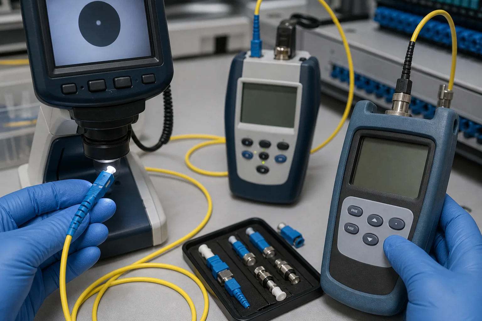
Insertion loss is typically measured using a light source and power meter (LSPM) or an optical loss test set (OLTS). The test setup must be clean and calibrated. The reference method is usually the “1-cord reference” or “3-cord reference” method, as described in the Fiber Optic Association’s testing guide. The 3-cord method is more accurate for connector loss measurement.
Return Loss Testing
Return loss is measured using an optical time-domain reflectometer (OTDR) or a dedicated return loss meter. The OTDR method is common for installed links, while a return loss meter is used for individual components. Ensure the test port is clean and the launch cable has a known RL value.
Visual Inspection
Before any optical test, inspect the connector end faces with a fiber inspection microscope. Dirt, scratches, or pits can cause high loss and reflections. The IEC 61300-3-35 standard defines cleanliness grades for connector end faces.
Standards Alignment
When specifying low-loss patch cords, reference the relevant standards. For example, IEEE 802.3db defines 100G/200G short-reach optical interfaces, which may have strict loss budgets. Ensure your patch cords meet the requirements of the optical modules you are using.
Design and Manufacturing Tradeoffs
Low-loss patch cords achieve superior performance through precision manufacturing and advanced materials. However, these improvements come with tradeoffs.
Ferrule Quality and Polish
The ferrule is the ceramic tip that holds the fiber. Low-loss connectors require a precise radius of curvature, apex offset, and fiber protrusion. These are controlled during polishing. A poor polish can lead to high IL and RL. Manufacturers use automated polishing machines and interferometric testing to ensure quality.
Connector Type
APC connectors have an 8° angle on the ferrule end face, which reduces reflections. However, they must be matched with other APC connectors; mixing APC with PC or UPC will cause high loss and damage. This is a critical consideration in design.
Cable Type
Bend-insensitive fibers (G.657.A1 or A2) allow tighter bends without added loss, but they may have slightly higher attenuation compared to G.652.D. For short patch cords, the difference is negligible, but for longer runs, it matters.
Cost
Low-loss patch cords are more expensive due to tighter tolerances and additional testing. The cost increase is often justified by improved network performance and reliability, especially in high-density environments.
Installation and Handling Implications
Even the best patch cord can fail if handled improperly. Here are key considerations:
- Bend radius: Do not exceed the minimum bend radius specified by the manufacturer (typically 10 mm for patch cords, but check the datasheet).
- Cleaning: Always clean connectors before mating. Use appropriate cleaning tools and inspect with a scope.
- Strain relief: Avoid pulling on the cable; use the connector boot for insertion/removal.
- Polarity: For MPO/MTP patch cords, ensure correct polarity (Type A, B, or C) to match your system.
Proper installation minimizes the risk of damage and maintains the low-loss characteristics.
Common Mistakes and How to Avoid Them
Engineers often make mistakes when selecting or testing low-loss patch cords. Here are the most common pitfalls:
- Assuming all low-loss are the same: Always verify IL and RL values on the datasheet.
- Skipping visual inspection: Dirty connectors cause high loss and reflections.
- Using the wrong test reference: Incorrect reference method leads to inaccurate IL measurements.
- Mixing connector polishes: APC and UPC are not interchangeable.
- Ignoring fiber type: Using G.652.D in tight bends can cause macro-bending loss.
- Not considering wavelength: Loss values differ at 1310 nm vs. 1550 nm; test at the operating wavelength.
Avoid these mistakes by following a clear acceptance procedure and training your team.
Procurement Checklist
When purchasing low-loss patch cords, use this checklist to ensure you get what you need:
- Define requirements: Specify IL, RL, connector type (LC, SC, MPO), polish (UPC/APC), fiber type (SM/MM, G.652/G.657), and length.
- Request datasheets: Ask for measured IL and RL values, not just typical.
- Check certifications: Ensure the product meets relevant IEC/ITU standards.
- Sample testing: Order samples and test them in your environment before bulk procurement.
- Inspect packaging: Each connector should have protective caps and be individually packaged.
- Document test results: Ask for test reports or certificates of conformance.
By following this checklist, you can avoid costly mistakes and ensure long-term reliability.
Conclusion
Low-loss fiber patch cords are critical components in high-performance networks. Acceptance criteria based on insertion loss, return loss, and other parameters ensure that these components perform as expected. By understanding the thresholds, testing methods, and potential pitfalls, you can confidently select and deploy low-loss patch cords.
At Liqiba, we offer a range of high-quality fiber patch cords that meet stringent acceptance criteria. Our quality assurance processes ensure that every product is tested and verified. Contact us today to discuss your requirements.
Frequently Asked Questions
What is the typical insertion loss for a low-loss LC patch cord?
Typically, low-loss LC patch cords have an insertion loss of ≤0.15 dB for single-mode and ≤0.10 dB for multimode, but always verify with the manufacturer's datasheet.
What is the difference between UPC and APC connectors?
UPC connectors have a flat polish with a slight curvature, giving a return loss of ≥50 dB. APC connectors have an 8° angled polish, providing ≥60 dB return loss. APC is preferred for high-speed or analog systems, but must not be mixed with UPC.
How do I test the insertion loss of a patch cord?
Use a light source and power meter (LSPM) with the 3-cord reference method. Clean and inspect connectors before testing, and ensure the source wavelength matches your application.
What is return loss and why is it important?
Return loss measures reflected light. High return loss (e.g., ≥50 dB) is desirable to prevent reflections that can disrupt laser sources and increase bit error rates.
Can I use a low-loss patch cord with standard connectors?
Yes, low-loss patch cords are compatible with standard connectors as long as the polish type (UPC/APC) and fiber type match. However, mixing APC with UPC will cause high loss and damage.
What standards apply to low-loss patch cords?
Key standards include IEC 61753-1 for performance categories, IEC 61300-3-4 for insertion loss testing, and ITU G.652/G.657 for fiber characteristics.
Complete topic guide: Fiber Optic Patch Cord Guide: Types and Selection.







