
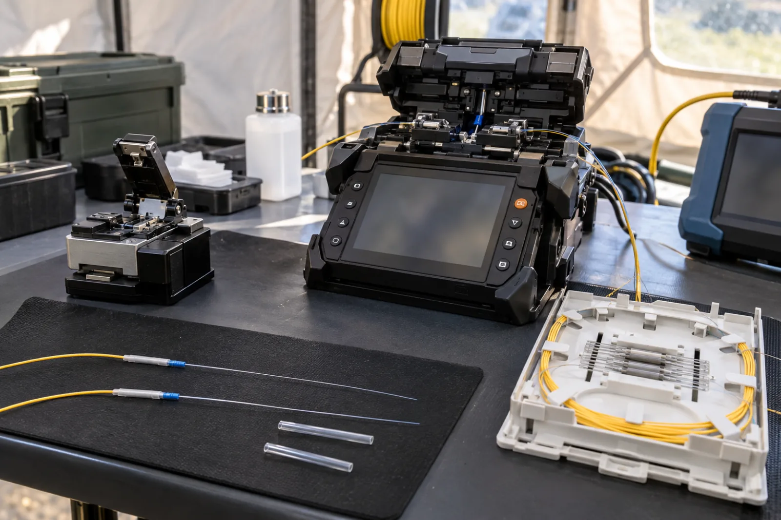
Summary: Practical fusion splice loss acceptance criteria begin with a project-defined limit and a documented test method. Do not accept or reject a splice from the fusion splicer’s displayed estimate alone. For event-level OTDR results, measure from both directions, match the same physical event, average the signed losses, and retain both traces with the final decision.
The numerical worksheet here is hypothetical. It explains the method and does not represent Liqiba production data or a universal contractual limit.
Separate the splicer estimate from optical evidence
A modern fusion splicer evaluates alignment, cleave geometry and the fused image, then displays an estimated loss. That estimate is valuable for immediate process control, but it is not a direct measurement of transmitted optical power.
The Fiber Optic Association’s fusion-splicing guide explains that the splicer estimate is not the optical test and that OTDR testing may be required. It also notes directional errors and the need for measurements from both ends when accurate splice loss is required.
FOA’s outside-plant splicing reference distinguishes end-to-end insertion loss from event localization. A source-and-power-meter test evaluates the complete link; it cannot isolate one permanent splice inside the span.
Define the acceptance rule before testing
The project specification should state fiber types, wavelengths, direction requirements, OTDR setup, launch and receive fibers, event-loss method, maximum averaged loss, handling of apparent gain, rounding and measurement uncertainty. If the specification only says “low-loss splice,” it is incomplete.
NECA/FOA 301 includes splice allowances in a cable-plant loss budget and instructs users to compare measured cable loss with the calculated value. Project owners may set different component targets, so the signed contract governs.
Why two OTDR directions can disagree
An OTDR estimates event loss by comparing backscatter levels before and after the splice. If the joined fibers have different mode-field or backscatter characteristics, the event can look like excess loss in one direction and apparent gain in the other. The physical splice does not amplify light.
Reverse-direction measurement exchanges the backscatter step. Averaging the two signed event values reduces this effect:
Bidirectional splice loss = (A-to-B event loss + B-to-A event loss) ÷ 2
Worked event-pairing example
Assume a single-mode route has three splices. The project’s hypothetical acceptance rule is a bidirectional average no greater than 0.10 dB at 1550 nm. The OTDR files use compatible pulse, wavelength, group index and analysis method. Distances from the far end are converted to the same route coordinate before pairing.
| Splice | A→B result | B→A result | Average | Decision against 0.10 dB |
|---|---|---|---|---|
| S1 | +0.18 dB | −0.06 dB | 0.06 dB | Pass |
| S2 | +0.27 dB | −0.01 dB | 0.13 dB | Investigate/fail |
| S3 | +0.09 dB | +0.05 dB | 0.07 dB | Pass |
For S1, (0.18 − 0.06) ÷ 2 = 0.06 dB. The negative value is retained as signed data; converting it to an absolute value would incorrectly produce 0.12 dB. For S2, (0.27 − 0.01) ÷ 2 = 0.13 dB, above the assumed limit.
Do not use this table’s 0.10 dB criterion without project approval. Fiber type combinations, network budget, operator rules and measurement uncertainty can justify a different limit.
Pair the same physical event
Distances read from opposite ends are not numerically identical coordinates. Use route length, launch and receive lead offsets, splice records and nearby landmarks to match events. A simple check is that the corrected distances from each end sum approximately to the installed span length, within distance uncertainty.
Our OTDR group-index distance guide explains why an incorrect index changes the scale. Our disclosed bidirectional OTDR case demonstrates route-coordinate reconciliation on an actual documented fiber path; its measured values are not limits for other projects.
Confirm trace quality before a remake
Check that the event lies in usable backscatter, away from an unresolved dead zone and above the noise region. Confirm pulse width, averaging, wavelength and range. A long pulse may merge nearby events; a short pulse may lack reach.
Inspect launch connections and ensure both traces represent the same installed condition. If the cable was disturbed, repaired or reconfigured between directions, averaging the files can be invalid. Preserve native trace files, not screenshots alone.
| Finding | Appropriate next action | Avoid |
|---|---|---|
| High one-way loss, opposite apparent gain | Pair and average directions | Rejecting on one direction only |
| Both directions high | Confirm setup, then follow remake rule | Editing the event table |
| Event inside dead zone | Adjust valid test setup or access plan | Reporting unsupported precision |
| Splicer estimate high, optical average passes | Apply governing acceptance hierarchy | Hiding either record |
Use a controlled remake decision
When the averaged optical result fails, verify identification and test quality before opening a closure. If remake is required, record the original fiber IDs, results, splice position, cause found, new splice estimate and post-repair optical results.
Repeated remakes consume fiber slack and can introduce handling risk. Set escalation criteria for insufficient slack, specialty-fiber mismatch, repeated cleave defects or abnormal splicer behavior. A supervisor or engineer should approve exceptions according to the project quality plan.
Control the splicing process before testing
Record splicer program, fiber identification, cleaver condition, electrode service status and environmental conditions required by the work instruction. Strip, clean and cleave with approved tools. Protect bare fibers from dust, wind and moisture, and dispose of fiber shards in a dedicated container.
A low estimated loss does not excuse a visible bubble, neck, offset or inadequate protector placement. Review both splicer camera axes where available. Perform the specified proof test, install the correct sleeve and allow it to cool before routing.
Route the protected splice in the tray without crossing the minimum bend radius or placing stress at the sleeve. Optical performance at the workbench does not prove long-term reliability if fibers are pinched under the tray cover or closure seal.
Define measurement uncertainty near the limit
When a calculated average lies close to the acceptance threshold, displayed resolution is not the same as measurement certainty. The test plan should define guard bands or other decision rules, the number of decimal places retained and how repeat acquisitions are handled.
For example, a 0.096 dB raw average displayed as 0.10 dB may appear exactly at a 0.10 dB limit, while a 0.104 dB result may also display as 0.10 dB. Preserve unrounded exports and apply the agreed rounding rule only at the decision stage.
Do not repeatedly reacquire until one trace passes and discard the rest. If repeatability is poor, investigate launch stability, connector condition, event analysis and instrument setup. Report the spread and the reason for selecting any governing result.
Manage ribbon and specialty-fiber exceptions
Mass fusion splicing produces multiple simultaneous joints. Evaluate each fiber where the test method provides lane-level data; a good ribbon average can conceal one high-loss fiber. Record ribbon orientation and fiber color mapping before closing the tray.
Dissimilar or specialty fibers may require validated splicer programs and different expectations. Never apply a standard G.652-to-G.652 target to a combination with materially different mode-field characteristics without engineering approval. Document the fiber pair and vendor guidance.
Connect component and link acceptance
Even when every visible splice meets its component criterion, the complete link must still meet the end-to-end insertion-loss budget. Fiber attenuation, connectors and other events add loss. Conversely, a link can meet the total budget while one splice exceeds a specified workmanship limit.
The commercial fiber optic tools page is the correct place to specify fusion splicer, cleaver, OTDR wavelengths, dynamic range and launch accessories. State fiber type and reporting requirements rather than asking only for a low displayed splice estimate.
Close the acceptance record with both directional files, paired event table, calculation formula, approved limit, uncertainty rule and disposition. That package makes the decision reproducible and prevents apparent OTDR gain from being mistaken for either excellent workmanship or impossible optical amplification.
Frequently Asked Questions
Is the fusion splicer loss estimate an acceptance test?
No. It is an equipment estimate based on alignment and image analysis. Project acceptance should use the specified optical test method and complete link evidence.
Why can an OTDR show a negative splice loss?
Different backscatter coefficients on the two fibers can make a splice appear as gain in one direction and higher loss in the other. Bidirectional averaging reduces this directional effect.
Is 0.1 dB a universal fusion splice limit?
No. It is often used as a practical target, but the governing contract, cable-plant budget, fiber combination and test method must define acceptance.
Should every high-loss splice be remade immediately?
First confirm trace quality, event location, launch conditions and bidirectional pairing. If the averaged result fails the agreed rule, follow the documented remake or engineering-disposition process.
Can end-to-end insertion loss identify one bad splice?
It can show that the complete link exceeds its budget, but it does not localize an individual permanent splice. An OTDR is normally used for event-level diagnosis.







