
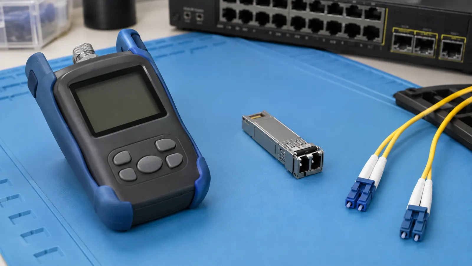
Summary: A DOM vs optical power meter reading difference is not automatically a faulty transceiver or cable. First verify that both readings represent the same direction, wavelength, optical boundary and operating condition. Digital optical monitoring provides module telemetry, while a suitable external meter measures light at its connected input. Reconcile those conditions before interpreting the difference or using it to estimate link loss.
This guide concerns a conventional point-to-point optical link. Its numerical examples are hypothetical, and its comparison worksheet is not a substitute for the exact transceiver, instrument and platform documentation. Burst-mode PON and multiwavelength coherent systems may require different measurement arrangements.
Identify what the module is reporting
DOM, also commonly described as digital diagnostic monitoring, can expose optical transmit and receive readings alongside other module operating information. The available fields, update behavior and supported modules depend on the platform. An unsupported field, stale value or administratively disabled interface should not be treated as a fresh optical measurement.
Cisco’s ASR 900 DOM documentation describes periodic collection of transmit power, receive power, bias current and supply voltage, with comparisons against warning and alarm thresholds. Its platform-specific note about administratively down ports illustrates why operating state belongs in the record.
Save the module identification, software version, port state and timestamp with the reading. Where a device provides several optical lanes, identify the lane and metric explicitly. A total power value and a per-lane value are different quantities even if both are expressed in dBm.
Draw the measurement boundary before disconnecting anything
Suppose the question is whether receiver power at end B agrees with an external reading. A measurement at transmitter A is not that comparison: the installed path lies between them. Likewise, a reading at the front of a patch panel differs from a reading after the equipment jumper connecting that panel to receiver B.
Sketch the source, installed fiber, panels, equipment cord and receiver. Mark the point where the meter will be connected, and list every component added or removed for the measurement. The small drawing prevents a surprisingly common mistake: blaming the instruments for loss introduced by a different test boundary.
Any disconnection may interrupt service. Obtain the operator’s maintenance authorization, identify the correct fiber and follow approved live-fiber and laser-safety procedures. Do not look into an optical port or assume a disconnected receive lead is dark. Establish safe power limits before connecting a meter.
Check units, wavelength and measurement mode
Absolute optical power in dBm is referenced to one milliwatt. Relative loss in dB is a ratio to a reference reading. A meter left in relative mode can therefore show a value that is numerically unlike the DOM field even when the optical setup is otherwise correct. Record the displayed unit instead of transcribing only the number.
FOA’s optical power measurement reference distinguishes absolute power from relative loss and explains wavelength-dependent detector calibration. Select the appropriate meter calibration and confirm that its detector range covers the expected signal. A convenient adapter does not establish wavelength or power compatibility.
For a multiwavelength signal, determine whether the external instrument reads aggregate power or separates the wavelength of interest. Avoid comparing an aggregate detector value with a module’s individual-channel estimate. State the supported scope of the comparison if the necessary selective instrument is not available.
Build a same-boundary comparison worksheet
Assume a stable, single-wavelength test arrangement. Receiver B reports −8.4 dBm. During an authorized interruption, a correctly configured meter reads −7.9 dBm at the end of the same equipment cord that normally mates to B. The observed difference, defined here as DOM minus meter, is −0.5 dB.
| Record field | Hypothetical entry | Reason to retain it |
|---|---|---|
| DOM receive value | −8.4 dBm at B | Identifies the receive metric and endpoint |
| External power | −7.9 dBm | Uses absolute power at the defined boundary |
| Signed difference | −8.4 − (−7.9) = −0.5 dB | Makes the subtraction convention explicit |
| Comparison status | Needs specified uncertainty limits | Prevents an unsupported pass or failure label |
This example assumes the source remains active and stable during the change from receiver to meter, and that connecting the meter does not alter source behavior. Verify those conditions in the actual system. If the transmitter shuts down or changes state after loss of the remote receiver, the two readings no longer describe the assumed condition.
Account for a temporary measurement lead
If an extra test lead is inserted and its loss is independently established as 0.3 dB at the test wavelength, a meter reading of −8.2 dBm after that lead corresponds to an estimated −7.9 dBm before it. The correction is an addition because the lead reduces received power. Keep the measured and corrected values in separate columns.
That correction is valid only for the stated boundary and characterized assembly. An additional mating connection or different adapter can change what has been included. Do not apply a generic patch-cord allowance to force the external reading to match telemetry; include the lead characterization and associated uncertainty in the record.
Use specifications to judge the discrepancy
There is no universal acceptable DOM-to-meter difference. Obtain the module’s monitoring accuracy specification for the relevant power and temperature range, together with the meter’s applicable uncertainty and the repeatability of the connection method. A receiver’s sensitivity specification is not its telemetry accuracy specification.
As a simple screening illustration, assume documented bounds of ±1.0 dB for telemetry and ±0.3 dB for the entire external measurement arrangement. The worst-case difference between their errors can reach 1.3 dB. The example 0.5 dB discrepancy is compatible with those assumed bounds, but this is not a formal calibration or a general acceptance rule.
The illustration does not justify adding every data-sheet number blindly. Bounds, standard uncertainties and coverage intervals have different meanings. Where contractual acceptance depends on the comparison, define the uncertainty treatment with the test owner. The site’s fiber measurement uncertainty guide provides related decision-rule context.
Distinguish a telemetry alarm from cable loss acceptance
A module alarm can be a useful operational signal, but it is not automatically the installation contract’s pass/fail threshold. Alarm tables may relate to the module’s supported operating range. A project can also require an engineering reserve, a specific link-loss measurement or other evidence beyond staying clear of an alarm.
Subtracting receive power at B in dBm from transmit power at A in dBm gives a telemetry-based path-loss estimate in dB only when the values, directions and timing are appropriate. Errors from both sensors and uncertainty about their reporting boundaries affect the result. Do not label that estimate a calibrated cable insertion-loss test.
For an installation handover requiring optical loss testing, use the agreed source-and-meter or OLTS method and reference procedure. Keep the in-service DOM snapshot as supplementary evidence. The power meter versus OTDR guide helps separate absolute power, end-to-end loss and event-location questions.
Investigate changes in a controlled order
Begin with identity and timing, then units and meter configuration, then the physical boundary. Only after those checks should a technician investigate connector contamination, a damaged jumper or a suspect module. Change one component at a time and preserve the before-and-after readings with the same labels.
When DOM drifts but the external measurement remains stable in repeated controlled comparisons, investigate telemetry behavior and operating conditions. When both values change similarly, investigate a real optical-path or source change. These patterns guide the next test; neither proves a particular failed component on its own.
For intermittent service, capture alarm timestamps, temperature and interface events before disturbing the connection. A clean reading after reseating a module may not explain the original failure. Document what was moved and avoid presenting a post-maintenance snapshot as evidence that the earlier condition never existed.
Order the test accessories that the method requires
For an inquiry through the fiber optic tools page, provide the signal wavelength, anticipated absolute power, connector type and polish, whether the path is live, and the measurement boundary. Include the required inspection accessories and reference leads, not just the meter body.
A useful final comparison report retains the raw telemetry, meter settings, setup drawing, corrections and stated limits. Its conclusion should distinguish agreement within the chosen method from a proven cable pass or a confirmed transceiver fault. That distinction makes the result actionable without overstating what two power numbers can demonstrate.
Frequently Asked Questions
Does a DOM reading have to equal an external meter reading?
Not exactly. Compare the same signal and boundary, then assess the difference using the applicable monitoring and measurement specifications.
Can transmit DOM and receive DOM certify cable insertion loss?
They can support an operational estimate under suitable conditions, but they do not replace the agreed calibrated loss-test method and reference procedure.
Why is dBm different from dB on a power meter?
dBm expresses absolute optical power relative to one milliwatt. A relative dB reading depends on the reference established for the measurement.
Can disconnecting the receiver change the comparison?
Yes. A disconnection can change source or link state. Verify that the external reading and telemetry represent comparable operating conditions.
Is there a universal allowable DOM-to-meter difference?
No. Use the exact module and instrument specifications, measurement boundary and project-approved uncertainty treatment.







