
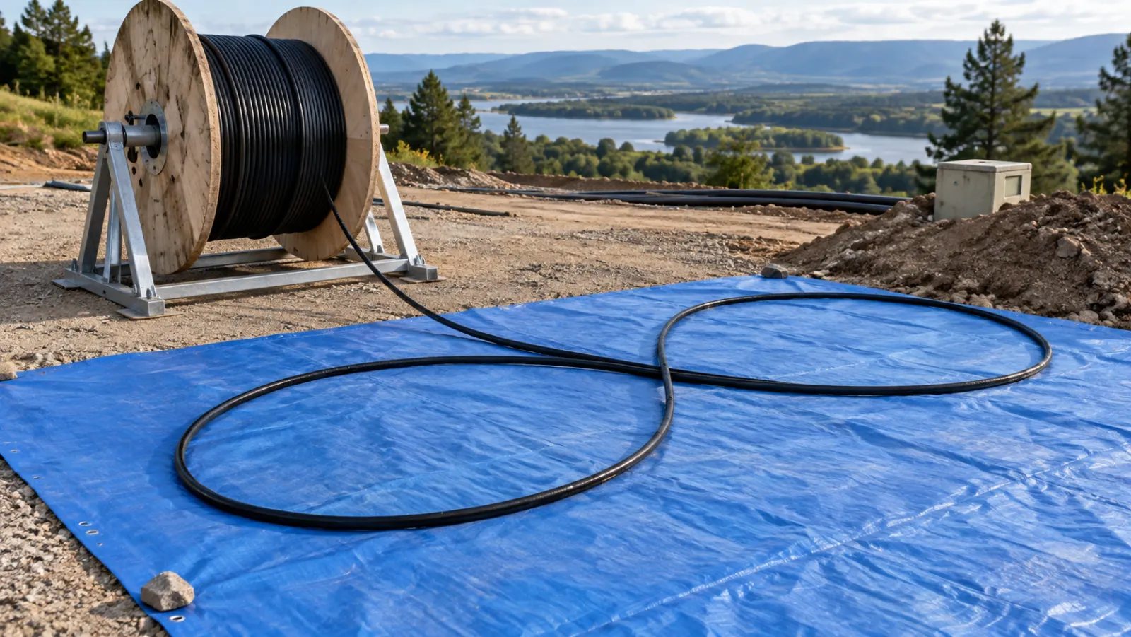
Summary: A fiber optic cable figure-eight handling procedure helps organize temporary cable storage between pulling stages without repeatedly introducing twist in the same direction. Success depends on the work area, cable-specific handling limits, payout order and communication between crews. The figure-eight pattern is not permission to exceed pulling tension, tighten a bend or drag a buried cable end through a pile.
This article concerns laying cable in broad alternating loops during installation. It is not a guide to tensioning a self-supporting aerial cable whose cross-section is called figure-eight. The planning calculations below are hypothetical and must be replaced with the actual cable and worksite information.
Decide why an intermediate storage area is needed
A continuous route may need more than one pulling stage because of access locations, route geometry, available equipment or a cable’s approved installation limits. In another arrangement, the reel is placed at an intermediate point and the cable is installed outward in two directions. These are different workflows with different requirements for which cable end must remain accessible.
FOA’s figure-eight installation reference describes both intermediate pulling and a midpoint payout arrangement. Its central principle is that alternating loops avoid accumulating twist in one direction. The practical lesson is to design the payout sequence before accumulating cable on the ground.
Identify the incoming route, outgoing route, reel location and intended next pulling end on a simple site sketch. If the crew cannot point to the next accessible end before work begins, the storage plan is incomplete. Do not rely on pulling whichever end happens to be visible once the pile has formed.
Separate cable geometry from site geometry
The approved cable data sheet should identify relevant bending and tensile limits and any restrictions on intermediate handling. A figure-eight needs enough room for both broad lobes, a gentle crossover and the approaches from the reel or duct. A large-looking overall pattern can still contain a tight bend where the cable enters it.
Use the cable bend-radius planning guide for the distinction between radius and diameter. The working radius at every change of direction matters, not simply the width of the tarpaulin. The pattern must remain within the manufacturer’s requirements while cable is moving as well as when it is resting.
Survey the ground for stones, protrusions, standing water and vehicle paths. Provide a suitable clean protective surface and controlled access. A clean sheet is useful for separating the jacket from dirt, but it does not protect the cable against a wheel, a sharp object underneath or excessive load at a crossing.
Make a preliminary footprint calculation
Assume a proposed arrangement uses two approximately circular lobes, each two metres in diameter, placed side by side. A simplified bounding rectangle is four metres by two metres. Adding an assumed one-metre working clearance around that rectangle produces a six-by-four-metre planning area, or 24 square metres.
| Planning item | Illustrative assumption | Calculated result |
|---|---|---|
| Lobe geometry | Two lobes, each 2 m diameter | Approximately 4 m × 2 m bounding box |
| Clearance | 1 m beyond each side | 6 m × 4 m reserved area |
| Reserved footprint | Rectangular estimate | 24 m² |
| Cable waiting between stages | 350 m at 0.10 kg/m | 35 kg of cable, excluding accessories |
This is a space-reservation exercise, not an installation drawing. It excludes crossover separation, actual lobe shape, duct approaches, reel stand, pulling equipment and traffic control. It also does not establish a safe stack height or lifting method. Add those requirements when the installation supervisor prepares the actual arrangement.
Check the assumptions against the cable
The assumed two-metre lobe diameter corresponds to a nominal one-metre radius only on the circular portions. It says nothing about the smallest radius at the crossover or entry. Compare each part of the proposed route with the cable-specific limit, and enlarge or redesign the area where needed.
The 35 kg example shows why a cable stack should not be treated as a light bundle merely because individual cable is flexible. Use actual mass per unit length and the amount staged. Any repositioning requires an appropriate handling plan, access and equipment; the arithmetic alone does not authorize a manual lift.
Control reel payout and the first layers
The reel should pay out using the approved stand and method, with its rotation controlled. Pulling loops over a stationary reel flange is not equivalent to rolling cable off a reel. Before releasing a long length, verify that the reel, guides and cable approach support the intended direction without introducing twist or abrupt bends.
FOA’s general cable installation guidance emphasizes manufacturer instructions, controlled pulling and avoiding twist during payout. Use that guidance alongside the exact cable documentation; generic rules are not a replacement for product-specific installation limits.
Inspect the first completed loops before allowing a large stack to develop. Check that the cable follows broad curves, that the crossover is not becoming a pressure point, and that the next length can settle without snagging. Small errors at the bottom are harder to correct after many additional layers are placed above them.
Define the next pulling end and any repositioning step
In an intermediate pull, the desired leading end may initially lie underneath the stored cable. A planned rearrangement may therefore be required before the next stage. Do not improvise by tugging that end through the stack: friction and local bends can occur where the crew cannot see them.
Where a midpoint workflow leaves the remaining reel end accessible above the laid-out cable, the handling sequence may avoid that particular rearrangement. Whether it is practical depends on reel orientation, available space and route access. Choose the workflow for the actual route rather than assuming one method always requires less labor.
Include a hold point before the next pull. The supervisor should confirm the correct end, unobstructed payout, approved pulling attachment, communication and remaining cable length. Keep the optical fibers out of the load path unless the cable’s approved design explicitly specifies how the pulling load is transferred.
Assign communication and stop conditions
One person should coordinate the transition between the pulling and cable-handling teams. Agree on clear start, slow and stop instructions and a backup when radio communication is lost. The operator at the puller may not see a loop tightening at the storage area, so local observations must be able to stop the work.
Stop if payout is obstructed, a crossover tightens, the cable twists visibly, an unexpected load develops or someone enters an unsafe position. Record the condition and correct the setup before restarting. Do not overcome a snag by increasing force while another crew member attempts to free the loop.
The pulling-tension and sidewall-pressure guide addresses separate mechanical checks along the route. A well-organized figure-eight does not guarantee that a duct bend, sheave or pulling attachment elsewhere remains within its limits.
Keep intermediate storage temporary and controlled
If work pauses, secure the area against vehicle access, unauthorized handling and contamination. Protect cable ends using the appropriate method for the cable construction. Record which end is intended to move next and what length remains, so another crew does not restart with an incorrect understanding of the sequence.
Do not describe a temporary outdoor laydown as an approved long-term storage method. Weather exposure, material compatibility and allowable storage conditions depend on the cable and packaging instructions. A plan for the next hour may be unsuitable for an unattended weekend.
Keep photographs of the arrangement as process records where authorized, with identifiable reference points and timestamps. A photograph can help explain handling conditions, but it does not prove compliance with an unseen bend radius or demonstrate that internal fibers remain undamaged.
Connect procurement information to the work plan
When requesting cable through the fiber optic cable supplier page, state the route sections, expected intermediate pulls, drum-length requirement and site constraints. Request the actual outer diameter, mass per length, installation limits, reel dimensions and permitted handling methods needed to develop the plan.
After installation, compare the recorded jacket condition and optical acceptance evidence with the project requirements. Retain any stop-event notes and approved corrective actions. The useful outcome of figure-eight handling is controlled cable movement and a traceable installation process, not a visually perfect coil that conceals an unreviewed mechanical problem.
Frequently Asked Questions
Is figure-eight handling the same as figure-eight aerial cable?
No. This guide describes a temporary cable laydown pattern, not a self-supporting cable cross-section or aerial tensioning procedure.
Why alternate the cable loops?
Alternating the direction of the loops helps avoid accumulating twist in one direction during temporary cable handling.
Is a two-metre loop diameter suitable for every cable?
No. The example is a preliminary footprint assumption. Verify the actual cable limits, crossover, approach geometry and worksite requirements.
Can I pull the bottom end through a cable stack?
Do not improvise that method. Plan access to the next pulling end and any required repositioning using the approved handling procedure.
Does a figure-eight eliminate pulling-tension checks?
No. Tension, bend radius, sidewall pressure and approved pulling attachments remain separate requirements throughout the route.







