
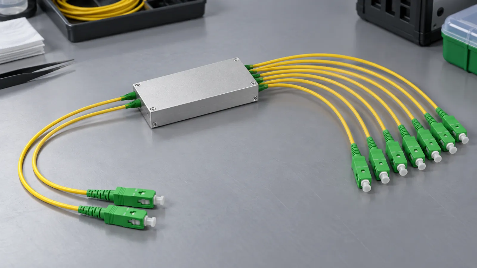
Summary: A 2xN PLC splitter loss budget must evaluate both feeder inputs to every required subscriber path. The splitter supplies passive optical connectivity; compatible equipment and configuration provide protection switching. Build separate primary and standby worksheets, use the actual specified port-to-port loss, and verify shared failure points before describing a PON as protected.
Draw the protection boundary first
In a dual-feeder arrangement, two OLT-side paths reach the two inputs of a splitter, while its outputs serve downstream branches. Those two inputs do not create twice as many subscribers. A 2×32 component still has 32 downstream outputs. The second upstream connection enables a supported protection architecture, but does not automatically duplicate the splitter, distribution fibers, drop fibers or subscriber equipment.
The Tellabs Type B protection application note describes this boundary and distinguishes arrangements within one OLT from those using separate OLTs. Its implementation-specific behavior also shows why switching capability cannot be inferred from a passive component alone. Review the entire supported system, including equipment, uplinks, power and configuration, rather than purchasing a two-input splitter and assuming the protection function is complete.
For basic component terminology, the PLC splitter selection guide provides background. This worksheet addresses a narrower question: whether each intended operating path has enough optical margin and a defensible acceptance record. It is not a configuration guide and does not authorize testing or disconnecting a live subscriber network.
Do not guess an extra loss from the input count
Obtain maximum insertion loss from each specified input to the relevant outputs across the required wavelengths and environmental conditions. Ask whether the value includes connectors, splices or only the bare device. Do not add an automatic 3 dB simply because the name begins with “2,” and do not assume the second input has no cost. The actual component and assembly boundaries govern the calculation.
As a product-specific example, CommScope lists its SP-23200NNNNXBBB bare 2×32 PLC splitter with stub-tail interfaces and a maximum splitter insertion loss of 17.7 dB. That published value belongs to that product, not to every 2×32 device or a Liqiba assembly. A connectorized module needs its own complete specification and evidence.
Describe the measurement planes
Put two vertical boundary marks on the proposed assembly drawing and state what is included between them. If the supplier’s loss covers the pigtails and device but excludes field splices, budget those splices separately. If a connector is already included in a complete assembly guarantee, do not count it again as an additional loss. An unclear boundary can make a conservative-looking spreadsheet wrong in either direction.
Build a two-path budget with explicit assumptions
Consider an entirely hypothetical downstream planning example for one selected subscriber branch. Assume an approved equipment design permits 29.0 dB of maximum path loss for this operating case, and reserve 3.0 dB for the project’s chosen engineering allowance. Assume the selected assembled splitter is specified at 18.0 dB, while the remaining shared distribution route contributes 1.4 dB. Neither value is a Liqiba product specification or a measured result.
Let feeder A be 6 km and feeder B be 10 km. For this example only, use a conservative planning coefficient of 0.35 dB/km at the wavelength under review, plus 0.8 dB of other feeder connections on each route. Feeder A contributes 2.1 + 0.8 = 2.9 dB; feeder B contributes 3.5 + 0.8 = 4.3 dB. The longer route therefore consumes 1.4 dB more before it reaches the common section.
| Assumed budget item | Feeder A route | Feeder B route |
|---|---|---|
| Feeder fiber | 2.1 dB | 3.5 dB |
| Other feeder connections | 0.8 dB | 0.8 dB |
| Specified splitter assembly | 18.0 dB | 18.0 dB |
| Shared distribution section | 1.4 dB | 1.4 dB |
| Calculated physical path loss | 22.3 dB | 23.7 dB |
| Path plus reserved allowance | 25.3 dB | 26.7 dB |
| Remaining below assumed 29.0 dB ceiling | 3.7 dB | 2.3 dB |
The important result is not that this imaginary network passes. It is that the standby path has less remaining allowance and must not inherit the primary path’s result. Repeat the worksheet for each required branch and wavelength, using the real component maxima and equipment limits. Upstream and downstream operating conditions differ; a downstream calculation does not close the upstream budget.
Check both the upper and lower loss boundaries
A worst-case maximum-loss worksheet addresses insufficient received power. The shortest, lowest-loss path also needs examination against the supported receiver-input range and any applicable minimum path loss. Do not use a nominal splitter value to represent both extremes. Record the relevant transmitter conditions and receiver limits for each operating state, including standby hardware that may have different documented characteristics.
Any required attenuator belongs in the appropriate route and wavelength budget. The Tellabs note, for example, distinguishes requirements for different card families; its settings must not be transplanted to an unrelated platform. Ask the equipment supplier to approve the optical design and identify version-specific conditions. For mixed-service measurements, the GPON and XGS-PON power-testing checklist explains why wavelength-selective evidence matters.
Evaluate failure diversity separately from optical margin
Two fibers in one cable can provide separate optical paths while sharing a single excavation risk. Two feeder cables entering the same damaged enclosure can also fail together. Mark common ducts, buildings, power sources, splitter locations and maintenance access on the route drawing. Distinguish component redundancy from route diversity. A loss-budget spreadsheet cannot prove that a network survives every relevant physical failure.
Likewise, two OLT ports do not necessarily protect against an entire chassis or controller failure. Cisco’s Routed PON deployment guide distinguishes OLT-, controller- and router-level behavior for its supported Type B implementation. The purchasing lesson is to name the failure scenarios and verify the exact platform and release, not to promise universal sub-second restoration.
Create a scenario register
For each proposed scenario, record the failed element, expected surviving path, required control action, permitted service interruption and verification method. Include a clear “not protected” designation for failures outside the agreed scope. This is more useful than a blanket resilient-network claim because operations staff can see which repairs still require urgent intervention and which maintenance actions may affect both paths.
Specify a splitter that can be accepted unambiguously
When requesting a PLC splitter quotation, identify the two upstream ports, output count, wavelength range, connector polish, packaging and exact loss boundary. Request input-to-output test records with clear port mapping rather than one unlabeled average. Confirm how unused ports are protected and what environmental conditions the supplied configuration supports. A bare component and a field-ready enclosure are different purchasing items.
Require a deviation list for any proposed substitute. A change in package, connectors or fiber exit direction can affect installation space and additional connection counts even when the nominal split ratio is unchanged. Review that change against both route budgets. Keep the approved drawing, optical specification and port-identification schedule together so a replacement can be checked without reconstructing the original design from memory.
Commission the protection function, not just the optics
Keep normal-operation acceptance and protection acceptance as separate sign-off items. The first confirms that the intended service works on the selected active route. The second confirms what happens when an agreed protected element becomes unavailable. Name the person authorized to initiate each test and the rollback condition. If a required scenario cannot be exercised safely before handover, record that limitation and an approved follow-up plan instead of marking it as demonstrated.
Within an authorized test window, obtain the specified optical records for both routes and then exercise the agreed protection scenarios using the equipment manufacturer’s procedure. Record traffic behavior, alarms, restoration conditions and whether the system returns automatically or remains on the surviving path. Do not perform uncontrolled fiber cuts or issue generic configuration commands on a live PON.
Archive the final primary and standby worksheets with the route drawing and commissioning results. If a later repair adds a connector or reroutes the standby feeder, update the affected budget before closing the change. Protection is a maintained system property: both paths, their common elements and the switching mechanism must remain consistent with the design that was actually accepted.
Frequently Asked Questions
Does a 2×32 splitter provide sixty-four subscriber outputs?
No. It has two upstream-side ports and thirty-two downstream outputs. The second input does not double the output count.
Should every 2xN budget automatically add 3 dB?
No. Use the specified maximum port-to-port loss and exact assembly boundary for the selected device and operating conditions.
Does a two-input splitter provide automatic protection switching?
No. It is a passive component. Compatible equipment, supported configuration and verified operating procedures provide the protection function.
Can the standby route use the primary route loss result?
No. Calculate and verify each route separately, including its length, connections, component conditions and required wavelengths.
Does Type B protection duplicate every downstream element?
No. A basic dual-feeder arrangement still has shared downstream elements. Identify the exact protected and unprotected failure scenarios in the system design.







