
What Is a PLC Fiber Splitter and Why Does It Matter?
A PLC (Planar Lightwave Circuit) fiber splitter is a passive optical component that divides one or two input optical signals into multiple output signals with precise, predetermined ratios. Unlike fused biconical taper (FBT) splitters, PLC splitters are fabricated using semiconductor lithography to create a waveguide pattern on a silica glass chip, enabling compact, high-performance splitting for a wide range of fiber optic networks. They are essential in passive optical networks (PON), fiber-to-the-home (FTTH) deployments, and test equipment, where they distribute signals to multiple users or monitor network performance. This guide covers the fundamental concepts, design parameters, and selection criteria you need to specify the right PLC splitter for your application.
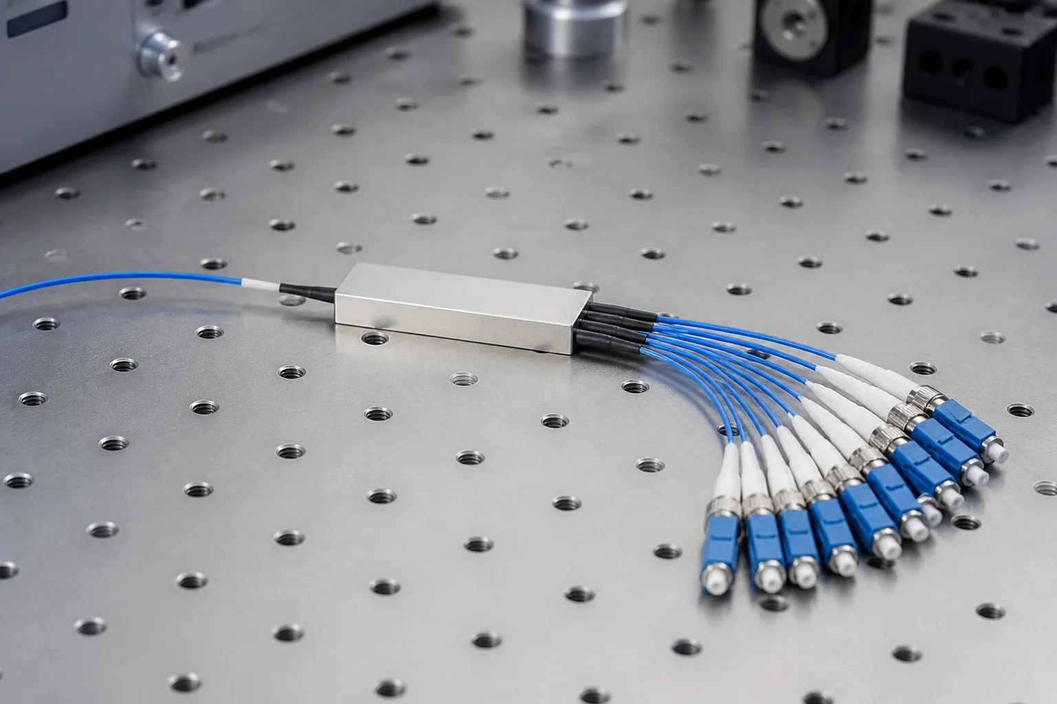
Essential Terminology and Definitions
Understanding the key terms used in PLC splitter datasheets and specifications is critical for accurate selection and deployment. Below are the most important definitions, with typical values noted where applicable.
Split Ratio and Configuration
The split ratio indicates the number of output ports and the proportion of optical power delivered to each. Common configurations include 1×2, 1×4, 1×8, 1×16, 1×32, and 1×64, as well as 2×N versions for redundant or bidirectional applications. The ratio is typically expressed as a percentage (e.g., 50:50 for 1×2) or as a power distribution in decibels (dB). For uniform splitters, the theoretical insertion loss is 10 × log10(N), where N is the number of outputs—for example, a 1×8 splitter has an ideal loss of about 9.03 dB. In practice, excess loss adds to this value.
Insertion Loss
Insertion loss (IL) is the total optical power loss from the input port to a given output port, expressed in dB. It includes the theoretical splitting loss plus excess loss (due to material absorption, scattering, and waveguide imperfections). Typical insertion loss values for a 1×32 PLC splitter are around 16.5–17.5 dB, but these are not standardized; always refer to the manufacturer’s data. Lower insertion loss is generally preferred, but it must be balanced with uniformity and cost.
Uniformity
Uniformity (or loss uniformity) is the maximum difference in insertion loss between any two output ports. It is a key quality metric, especially in PON systems where consistent signal levels across users are desired. Typical uniformity for a 1×32 PLC splitter is ≤1.5 dB, but again, this is a typical value, not a normative requirement.
Return Loss
Return loss (RL) measures the amount of light reflected back toward the source, expressed in dB. Higher return loss values indicate better performance (less reflection). For PLC splitters, return loss is typically ≥50 dB for single-mode applications, which is a typical engineering value, though some standards may specify minimum values for specific applications.
Polarization Dependent Loss (PDL)
Polarization dependent loss is the maximum variation in insertion loss as the input polarization state changes. It is particularly important in systems where polarization may drift, such as in high-speed coherent transmission. Typical PDL for PLC splitters is ≤0.3 dB.
Operating Wavelength Range
PLC splitters are designed for specific wavelength bands, commonly 1260–1650 nm for single-mode applications, covering O-, E-, S-, C-, and L-bands. This range is typical for telecommunications, but some splitters may be optimized for narrower bands (e.g., 1310 nm or 1550 nm) for specific uses. The wavelength range affects the waveguide design and material selection.
Fiber and Connector Types
PLC splitters are available with various fiber types (e.g., G.652.D single-mode, G.657.A1 bend-insensitive) and connector types (e.g., SC, LC, FC) or as bare fiber pigtails. The choice depends on the application environment and mating requirements. For example, FTTH drop cables often use SC/APC connectors to minimize reflections.
Role of PLC Splitters in Fiber Optic Networks
PLC splitters serve as the central distribution point in point-to-multipoint (P2MP) architectures, enabling a single optical line terminal (OLT) to serve many optical network units (ONUs). They are also used in monitoring systems, where a small fraction of the signal is tapped for testing without disrupting service.
Passive Optical Networks (PON)
In PON systems (e.g., GPON, EPON, XGS-PON), a PLC splitter is placed between the OLT and the ONUs. It splits the downstream signal from the OLT to multiple ONUs and combines the upstream signals from the ONUs back to the OLT. The split ratio (e.g., 1:32 or 1:64) determines the number of subscribers that can share a single fiber. PLC splitters are preferred over FBT splitters in PON because they offer better uniformity, lower insertion loss, and more compact packaging for high port counts.
Fiber-to-the-Home (FTTH) Deployments
In FTTH networks, PLC splitters are often located in fiber distribution hubs (FDHs) or street cabinets, where they distribute signals to individual homes. They can be installed in central offices, outside plant enclosures, or inside buildings, depending on the network topology. The choice of splitter ratio and placement affects the optical power budget and the number of users served.
Test and Measurement
In test equipment, PLC splitters are used to tap a portion of the signal for monitoring or to split a signal for multiple test instruments. They are also used in optical time-domain reflectometer (OTDR) systems to isolate the test signal from the live network.
Key Engineering Decisions When Selecting a PLC Splitter
Selecting the right PLC splitter involves several trade-offs. Here are the critical decisions you must make:
1. Split Ratio and Port Count
Determine the number of outputs needed based on your network design. Higher port counts (e.g., 1×64) reduce the number of splitters required but increase insertion loss and may require higher-power transmitters. Consider future scalability: will you need to add more users later? If so, a modular approach with multiple splitters might be more flexible.
2. Packaging and Form Factor
PLC splitters come in various packages: bare fiber, blockless, fan-out, cassette, or rack-mount. The choice depends on installation environment (indoor/outdoor), space constraints, and cable management. For example, outdoor cabinets require ruggedized packaging with IP-rated enclosures, while data centers may use high-density cassette modules.
3. Connector Type and Polish
Select connectors that match your existing infrastructure. For single-mode systems, APC (angled physical contact) connectors are often used to achieve low return loss, especially for high-speed or analog video applications. UPC (ultra physical contact) connectors are also common. Ensure the connector polish is compatible with the splitter’s return loss requirements.
4. Environmental Specifications
Consider the operating temperature range, humidity, and mechanical durability. PLC splitters are typically rated for -40°C to +85°C, but verify that the chosen product meets your environmental conditions. For outdoor use, look for Telcordia GR-1209 and GR-1221 compliance, which are industry standards for reliability, though these are not mandatory for all applications.
5. Optical Performance Trade-offs
Balance insertion loss, uniformity, and PDL. Lower insertion loss often comes at a higher cost due to tighter manufacturing tolerances. For PON, uniformity is critical to ensure all users receive adequate signal; for monitoring, PDL may be more important. Use the optical power budget to calculate the maximum allowable loss for each output.
6. Cost and Supplier Reliability
Evaluate total cost of ownership, including initial purchase, installation, and maintenance. Choose a reputable supplier with proven quality control and testing procedures. Ask for test data for each unit to verify performance.
By carefully considering these factors, you can select a PLC splitter that meets your technical requirements and budget, ensuring reliable network performance.
PLC Splitter Architectures: From Wafer to Network Topology
At the component level, a PLC fiber splitter is a planar lightwave circuit fabricated on a silica or silicon substrate. The waveguide pattern defines the split ratio and the uniformity of the power division. However, from a network design perspective, the architecture of the splitter—how the chip is packaged and how the ports are arranged—determines how it integrates with the rest of the passive optical network.
1×N vs. 2×N Splitters
The most fundamental architectural choice is the number of input ports. A 1×N splitter has a single input and N outputs, while a 2×N splitter has two inputs and N outputs. The 2×N configuration is often used in redundant or dual-fiber systems, where one input is active and the other is a protection path. In standard PON deployments, 1×N splitters are the norm, with common split ratios of 1×2, 1×4, 1×8, 1×16, 1×32, and 1×64.
The choice between 1×N and 2×N affects not only the chip design but also the packaging. 2×N splitters require a more complex waveguide layout and typically have slightly higher insertion loss due to the additional input coupling. For most FTTH applications, a 1×N splitter is sufficient and more cost-effective.
Package Styles: Bare, Block, and Cassette
PLC splitters are available in several package styles, each suited to different installation environments:
- Bare fiber splitter: The chip is protected by a steel tube, with bare fiber pigtails exiting both ends. This is the most compact form and is often used inside larger enclosures or spliced directly to distribution cables.
- Block or box splitter: A ruggedized package with fiber pigtails terminated with connectors (e.g., SC/APC or LC/APC). This is the most common type for indoor installations, such as in telecommunication rooms or customer premises.
- Cassette or tray splitter: A module that fits into standard fiber management trays or racks. Cassettes are ideal for high-density applications, such as central offices or data centers, where multiple splitters must be organized and protected.
- Rack-mount splitter: A larger chassis that holds multiple splitter modules, providing even higher port density. These are used in headends or large distribution points.
The package style does not change the optical performance of the splitter chip, but it affects the physical footprint, cable management, and installation time. For example, a cassette allows for pre-terminated connectors and easy patching, while a bare splitter requires splicing and is more suitable for buried or aerial closures.
Split Ratio and Cascading
In a PON, the split ratio can be achieved in a single stage or by cascading multiple splitters. For instance, a 1×32 split can be implemented as one 1×32 splitter or as a 1×4 splitter followed by four 1×8 splitters. Cascading is often used to distribute splitters closer to the subscribers, reducing the length of drop fibers. However, each additional splitter adds insertion loss and splice points, so the overall link budget must be carefully calculated.
Typical split ratios follow powers of two, but non-standard ratios are possible for specialized applications. The choice of ratio is a trade-off between the number of subscribers served and the optical power available to each. A higher split ratio reduces the power per port, which may limit the reach or data rate.
Comparison of PLC Splitter Types
The following table summarizes the key characteristics of the main PLC splitter architectures. Note that the values listed are typical engineering values, not normative requirements, unless otherwise indicated.
| Architecture | Input Ports | Typical Split Ratios | Insertion Loss (dB) | Package Options | Primary Use Cases |
|---|---|---|---|---|---|
| 1×N | 1 | 1×2, 1×4, 1×8, 1×16, 1×32, 1×64 | 3.5 – 20 (increases with N) | Bare, block, cassette, rack | Standard PON, FTTH |
| 2×N | 2 | 2×2, 2×4, 2×8, 2×16, 2×32 | Similar to 1×N plus ~0.5 dB extra | Bare, block, cassette | Redundant systems, dual-fiber |
| 1×N (cascaded) | 1 (per stage) | e.g., 1×4 + 4×1×8 = 1×32 | Sum of each stage plus splice losses | Any combination | Distributed splitting, flexible network design |
| 2×N (cascaded) | 2 (per stage) | e.g., 2×2 + 2×1×4 = 2×8 | Sum of each stage plus splice losses | Any combination | Redundant distributed networks |
Insertion loss values are typical for standard single-mode splitters operating in the 1260–1650 nm range. The exact loss depends on the split ratio, the quality of the chip, and the connector/splice losses. For a 1×32 splitter, for example, the theoretical minimum loss is about 15 dB (10 log10(32)), but practical devices typically have an insertion loss of 16.5 to 17.5 dB, including excess loss.
Selection Criteria for PLC Fiber Splitters
Choosing the right PLC fiber splitter involves more than just picking a split ratio. The following criteria should guide your decision:
Network Topology and Split Ratio
First, determine the required split ratio based on the number of subscribers and the optical budget. In a GPON network, for example, a 1×32 splitter is common, but 1×64 is possible with higher-power transceivers. The split ratio directly affects the insertion loss and the number of subscribers per fiber.
Operating Wavelength
PLC splitters are typically designed for the 1260–1650 nm range, covering O-band to L-band. However, some applications may require operation in a narrower band, such as 1310 nm for upstream and 1490 nm for downstream in GPON. Ensure the splitter’s wavelength range matches your system’s transmission windows.
Fiber and Connector Types
The splitter’s pigtails and connectors must match the rest of your network. Common connector types are SC, LC, and FC, with APC polish (8° angled) for PON applications to minimize reflections. Bare fiber splitters are spliced directly to the network fiber, eliminating connector loss but requiring splicing expertise.
Environmental and Mechanical Requirements
Consider the installation environment. Outdoor splitters may require a ruggedized package with IP-rated enclosures, while indoor splitters can be in standard cassettes. Temperature range, humidity, and vibration resistance are important for long-term reliability. Most commercial splitters meet Telcordia GR-1221 for environmental testing, but verify the specific ratings for your application.
Compliance and Standards
While there is no single global standard for PLC splitters, they are often tested to Telcordia GR-1209 and GR-1221, which define reliability and quality requirements. In addition, IEC 61753-1 defines generic performance standards for fiber-optic interconnecting devices. Ensure that the splitter you select complies with relevant industry standards, but note that these are typically performance requirements, not design specifications.
Performance Limits and Design Tradeoffs
Every PLC splitter has inherent performance limits that must be balanced against cost and application needs.
Insertion Loss and Split Ratio
The insertion loss increases logarithmically with the split ratio. A 1×2 splitter has a typical insertion loss of 3.5–4.0 dB, while a 1×64 splitter has a typical loss of 19–20 dB. This loss directly reduces the optical power available at each output, limiting the reach and data rate. For high split ratios, you may need to use higher-power transmitters or optical amplifiers, which increase system cost.
Uniformity and PDL
Uniformity—the variation in output power across ports—is a critical parameter. Poor uniformity means some subscribers receive less power, which can degrade performance. Typical uniformity for a 1×32 splitter is around 1.5–2.0 dB. Polarization dependent loss (PDL) is another concern, especially in systems with polarization-sensitive components. PDL should be kept below 0.3 dB for most applications.
Return Loss and Reflectance
Return loss measures how much light is reflected back toward the source. In PON systems, high reflectance can interfere with the laser and cause bit errors. APC connectors provide a return loss of >60 dB, while UPC connectors offer >50 dB. For splitter chips, the return loss is typically >55 dB, but the connector polish is the limiting factor.
Bandwidth and Wavelength Dependence
PLC splitters are inherently wavelength-dependent, but the variation is usually small within the specified range. However, at the edges of the operating band, insertion loss may increase slightly. Some high-performance splitters are optimized for a specific wavelength, such as 1550 nm, to minimize loss.
Cost vs. Performance
Higher split ratios and better uniformity come at a cost. A 1×64 splitter is more expensive than a 1×32, and premium chips with tighter uniformity may cost more. In many cases, a well-designed network can tolerate a slightly higher insertion loss if it reduces overall cost. Always perform a link budget analysis to determine the acceptable performance range.
In summary, the selection of a PLC fiber splitter is a balancing act between split ratio, insertion loss, package style, and cost. By understanding the architectural options and performance tradeoffs, you can choose a splitter that meets your network’s requirements without over-specifying.
Planning Calculations: Sizing the Splitter Before You Buy
Before specifying a PLC fiber splitter, you must calculate the optical budget and verify that the splitter’s loss fits within it. The optical budget is the difference between the transmitter output power and the receiver sensitivity, minus all system losses. For a PON, the ITU-T G.984.x and G.987.x series define classes (e.g., B+, C+) with specific loss ranges, but these are normative requirements for the entire link, not just the splitter. In practice, you allocate a portion of the budget to the splitter, connectors, splices, and fiber attenuation.
Calculating Splitter Loss
The theoretical loss of a 1×N splitter is 10 × log10(N) dB. For example, a 1×8 splitter has a theoretical loss of 9.0 dB. However, real PLC splitters have excess loss, which is the additional loss beyond the theoretical value. Typical excess loss for a well-made PLC splitter is 0.5–1.5 dB, but this is not a standard limit—it varies by manufacturer and quality. Always use the maximum insertion loss specified by the vendor, not the typical value, for worst-case budgeting.
For a 1×32 splitter, the theoretical loss is 15.0 dB, and the maximum insertion loss might be around 16.5–17.5 dB, depending on the package and connector type. This is a typical engineering value, not a normative requirement. Always check the datasheet.
Power Budget Example
Consider a GPON system with a Class B+ optical budget of 28 dB (normative per ITU-T G.984.2). If you use a 1×32 splitter with a maximum loss of 17.0 dB, you have 11 dB left for fiber, connectors, and splices. If the fiber run is 10 km with a loss of 0.35 dB/km (typical for G.652.D at 1310 nm), that’s 3.5 dB. Add 2 dB for connectors and splices (typical), leaving 5.5 dB of margin. This is acceptable, but if you add another splitter stage, you must recalculate.
Cascaded Splitters: Summing Losses
When cascading splitters, the total loss is not simply the sum of the individual splitter losses because the second splitter divides the already-split signal. For a 1×4 followed by a 1×8, the total split ratio is 1×32, but the loss is the sum of the two splitter losses: 7.2 dB (1×4) + 10.5 dB (1×8) = 17.7 dB, plus any connector losses between them. This is higher than a single 1×32 splitter, which might have a loss of 17.0 dB. Cascading adds complexity and loss, so it’s usually only used for flexibility in fiber routing.
Installation Implications: Physical and Optical Considerations
Installation of a PLC fiber splitter involves more than just plugging in connectors. The physical environment and handling can affect performance and longevity.
Bend Radius and Fiber Management
PLC splitters have input and output pigtails that are sensitive to bending. The recommended minimum bend radius for standard G.657.A1 fiber is 10 mm, but for pigtails, it’s safer to maintain at least 30 mm to avoid micro-bending losses. In splice closures and distribution frames, use bend-limited fiber guides. Never kink or tightly coil the pigtails.
Connector Cleaning and Inspection
Dirty connectors are a common cause of high insertion loss and reflectance. Before mating any connector, inspect the end face with a scope and clean it with a dry or wet cleaning method. This is critical for PLC splitters because the splitter itself has low loss, but a dirty connector can add 0.5 dB or more. In outdoor installations, use dust caps until the moment of connection.
Environmental Sealing
If the splitter is installed in an outdoor cabinet or closure, ensure it is rated for the environment. Most PLC splitters are not hermetically sealed; they rely on the enclosure for protection. Check the operating temperature range: typical commercial splitters operate from -40°C to +85°C, but this is a typical value, not a universal standard. For extreme environments, specify a hardened splitter.
Polarity and Fiber Orientation
For 2×N splitters, polarity matters. In a 2×32 splitter, the two input fibers correspond to different sets of output fibers. Misconnecting the inputs can cause the wrong ONUs to receive signals. Always label the input and output fibers clearly. In cassette-type splitters, the orientation is usually marked, but for bare splitters, you must trace the fibers.
Testing and Quality Assurance: Verifying Performance
After installation, you must test the splitter to ensure it meets specifications. This involves both insertion loss and return loss measurements.
Insertion Loss Testing
Use an optical light source and power meter (OLTS) to measure insertion loss. For a PLC splitter, you need to test each output port individually. The test setup should include reference test cords and a launch cable to eliminate the effect of the source. The measured loss should be within the vendor’s specified maximum. For example, if the datasheet says maximum insertion loss is 17.5 dB for a 1×32, your measurement should be at or below that. Note that the measurement includes the connector losses on the test cords, so use high-quality reference-grade connectors.
Return Loss Testing
Return loss is measured with an OTDR or a return loss meter. The return loss of a PLC splitter is typically >50 dB, but this is a typical value. For PON systems, the return loss requirement is often specified in the system standard, such as >50 dB for the entire link. If you measure a low return loss, check for dirty connectors or poor splices.
OTDR Testing: Interpreting Traces
An OTDR can be used to verify the splitter’s presence and loss. However, OTDR testing through a splitter is tricky because the splitter creates a large loss event, and the backscatter from the drop fibers is attenuated. For a 1×32 splitter, the OTDR trace will show a significant drop at the splitter, but you may not see events beyond the splitter clearly. To test individual drop fibers, you need a high-resolution OTDR or use a light source and power meter at the ONU side.
Documentation and Traceability
Keep a record of all test results, including the date, tester ID, splitter serial number, and measured loss per port. This is important for troubleshooting and for warranty claims. Many vendors provide a test report with the splitter, but you should also perform your own acceptance testing upon delivery.
Field Examples and Common Pitfalls
Real-world deployments often reveal issues that are not obvious in the datasheet. Here are a few examples and caveats.
Example 1: Underestimating Connector Loss
In a FTTH deployment, a technician installed a 1×16 splitter with a maximum loss of 13.5 dB. The power budget allowed for 15 dB of splitter loss, so they thought they had 1.5 dB margin. However, they used cheap patch cords with high insertion loss (0.5 dB per connector) and had two connectors on each side, adding 2 dB total. The actual loss was 15.5 dB, exceeding the budget. The fix was to use low-loss connectors and minimize the number of connections.
Example 2: Dirty Connectors in a Cassette
A cassette-type splitter was installed in a data center, but the link had intermittent errors. The OTDR showed no major faults, but the power meter measured a 1 dB higher loss than expected. Inspection revealed a dirty connector on the input port of the cassette. Cleaning the connector restored the expected loss. This highlights the importance of cleaning even in indoor environments.
Caveat: Splitter Uniformity and PON
In a PON, the splitter’s uniformity (the difference in loss between the best and worst output ports) can affect the power received by different ONUs. If one ONU receives too little power, it may not work. Typical uniformity for a 1×32 PLC splitter is around 1.5 dB, but this is a typical value. When planning, use the maximum insertion loss for the worst port, not the average. Also, consider the PON class: if you are using a higher-class PON (e.g., C+), the splitter loss is less critical, but you still need to stay within the total budget.
Caveat: Wavelength Dependence
PLC splitters are wavelength-flat over the typical PON wavelengths (1310 nm, 1490 nm, 1550 nm), but the insertion loss can vary slightly with wavelength. The datasheet usually specifies loss at a reference wavelength, such as 1550 nm. If you are using a different wavelength, check the loss at that wavelength. For example, the loss at 1310 nm may be 0.2 dB higher than at 1550 nm. This is a typical variation and is usually within the specification.
By carefully planning your optical budget, installing with proper handling, and testing thoroughly, you can avoid common pitfalls and ensure reliable operation of your PLC fiber splitter network.
Failure Modes and Common Mistakes in PLC Splitter Deployments
Even a well-designed PLC fiber splitter can fail prematurely or underperform if installation and operation introduce avoidable errors. Understanding the typical failure modes and common mistakes helps you plan preventive measures and avoid costly field rework.
Mechanical and Environmental Failure Modes
PLC splitters are passive components, but they are not immune to mechanical stress. The most frequent mechanical failures include:
- Fiber breakage at the chip interface – caused by excessive bending or pulling of pigtails during installation.
- Connector ferrule damage – from improper mating or repeated insertions without cleaning.
- Housing seal failure – allowing moisture ingress in outdoor or industrial environments.
Thermal cycling can also induce stress on solder joints or adhesive bonds inside the package. While PLC splitter packages are typically designed for a wide temperature range (e.g., -40°C to +85°C is common, but always verify with the manufacturer), rapid temperature changes can cause micro-cracks if the module is not properly strain-relieved.
Optical Failure Modes
Optical failures are often subtle and may only appear after months of operation:
- Increased insertion loss – often due to contaminated connectors or micro-bends in the fiber.
- Return loss degradation – caused by poor connector mating or dirt on the end face.
- Wavelength-dependent loss – some splitters exhibit higher loss at certain wavelengths; this is a design characteristic, but excessive deviation can indicate a defective unit.
In PON systems, a common mistake is to assume that all splitter outputs have identical loss. While uniformity is specified, typical uniformity values are around 0.5 to 1.5 dB, but they are not a guarantee of perfect balance. Always check the datasheet for the specific splitter.
Common Installation and Design Mistakes
Beyond physical damage, several engineering errors recur:
- Underestimating connector loss – every mated connector adds loss; a typical connector loss is 0.2 to 0.5 dB, but it can be higher if not properly cleaned. Summing all connector losses in a link budget is essential.
- Ignoring polarity – in multi-fiber splitters, incorrect polarity mapping can cause complete service failure. Always verify the polarity scheme (e.g., TIA-568 or custom) before installation.
- Using the wrong splitter type – for example, using a 1×32 when a 1×16 would suffice, unnecessarily increasing loss and cost.
- Poor fiber management – exceeding the minimum bend radius during routing can cause micro-bends, increasing loss and potentially leading to fiber breakage over time.
Another frequent mistake is neglecting to test the splitter after installation. A pre-installation test may pass, but handling and installation can introduce damage. Post-installation OTDR testing can verify the integrity of the splitter and the entire link.
Procurement Checklist for PLC Fiber Splitters
To ensure you select the right PLC fiber splitter, use a structured checklist. This helps you compare products objectively and avoid missing critical specifications.
Key Specifications to Verify
- Split ratio and configuration – e.g., 1×8, 2×16, etc. Ensure it matches your network design.
- Operating wavelength range – typically 1260–1650 nm for PON applications, but confirm it covers your specific wavelengths.
- Insertion loss (maximum and typical) – maximum loss is a guaranteed limit; typical values are for reference only.
- Return loss – usually specified as minimum, e.g., 50 dB for PC, 60 dB for APC. Ensure it meets your system requirements.
- Uniformity – the maximum difference in loss between outputs. Lower uniformity is better for balanced PON links.
- Directivity – isolation between input ports (for 2xN splitters). Typical values are above 55 dB.
- Pigtail length and connector type – SC/APC is common in PON, but LC or others may be required.
- Package type – bare, cassette, module, or rack-mount. Choose based on your installation environment.
Compliance and Documentation
Ensure the splitter meets relevant industry standards, such as Telcordia GR-1209 and GR-1221 for reliability, or IEC 61753-1 for performance categories. These standards define test procedures and pass/fail criteria. Request the manufacturer’s test report and datasheet to verify compliance.
Also check that the splitter has proper traceability – serial numbers, date codes, and test data. This is crucial for warranty claims and future troubleshooting.
Supplier Qualification
Evaluate the supplier’s manufacturing capabilities and quality control processes. Ask for sample units for independent testing. A reputable supplier should be willing to provide technical support and customization options.
Lifecycle Maintenance and Monitoring
PLC splitters are passive and generally require minimal maintenance, but they are not maintenance-free. A proactive approach extends their lifespan and ensures consistent performance.
Inspection and Cleaning Schedule
Connectors are the most vulnerable part of a splitter. Establish a routine inspection schedule, especially for connectors that are frequently mated and unmated. Use a fiber inspection microscope to check for contamination, and clean with appropriate tools (dry cleaning or solvent-based) when needed. Always clean before every connection, even if the connector appears clean.
Environmental Monitoring
If the splitter is installed in an outdoor enclosure, regularly check the enclosure for moisture, dust, or pest intrusion. Verify that seals are intact and that the enclosure’s environmental rating (e.g., IP65) is still valid. In high-humidity areas, consider adding desiccant packs if the enclosure allows.
Performance Trending
For critical networks, consider periodic OTDR testing to measure insertion loss and reflectance of the splitter. Record the results and compare them to baseline measurements. A gradual increase in loss may indicate contamination or micro-bending, while a sudden spike could signal fiber breakage. Trending helps you identify issues before they cause service degradation.
Spare Parts and End-of-Life Considerations
Keep spare splitters in stock for quick replacement, especially for high-availability networks. PLC splitters have a long lifespan (typically 20+ years), but they can be damaged by unforeseen events. When decommissioning, ensure proper disposal of fiber and packaging per local regulations.
Actionable Recommendations and Conclusion
To get the most out of your PLC fiber splitter deployment, follow these practical guidelines:
- Design with margin – include connector losses and a safety margin (e.g., 1-2 dB) in your link budget to accommodate aging and environmental factors.
- Test before and after installation – always perform insertion loss and OTDR tests to verify the splitter’s performance and detect any installation damage.
- Document everything – record splitter serial numbers, test results, and installation locations. This simplifies troubleshooting and warranty claims.
- Train installation personnel – emphasize proper handling, cleaning, and bend radius control to minimize human errors.
- Choose quality over price – a cheap splitter may save money upfront but can lead to higher loss, lower reliability, and more frequent replacements.
In conclusion, a PLC fiber splitter is a reliable and cost-effective solution for distributing optical signals in PON and other networks. By understanding its failure modes, following a rigorous procurement process, and implementing lifecycle maintenance, you can ensure long-term performance and avoid common pitfalls. Remember that passive components are only as good as their installation and care. With proper planning and attention to detail, your PLC splitter network will deliver stable, high-quality service for years to come.
Frequently Asked Questions
What is a PLC fiber splitter and how does it differ from a fused biconical taper (FBT) splitter?
A PLC (Planar Lightwave Circuit) splitter uses a silica glass chip with optical waveguides to split light evenly, offering high stability and compact size. In contrast, FBT splitters are made by fusing and tapering fibers, which can be less uniform and more wavelength-dependent. PLC splitters are preferred for FTTH and high-density applications due to their reliability and consistent performance across wavelengths.
How do I choose between 1xN and 2xN PLC splitters for my fiber network?
Choose a 1xN splitter when you need to distribute one input signal to multiple outputs, typical in PON networks. Use a 2xN splitter when you need two input fibers, often for redundancy (e.g., dual-homing) or to support two separate services. Consider the number of subscribers, future scalability, and whether you need backup paths. Ensure the split ratio matches your optical budget.
What are the typical insertion loss and uniformity specifications for PLC splitters, and how do they affect network design?
Typical insertion loss for a 1×8 PLC splitter is around 10.5 dB (max), and uniformity is within 1.5 dB. Higher split ratios (e.g., 1×32) have higher loss (around 17 dB). These losses must be accounted for in your optical link budget. Uniformity ensures consistent power across outputs, which is critical for equal signal quality to all subscribers. Always verify specs from the manufacturer.
Are PLC splitters compatible with both single-mode and multimode fiber systems?
PLC splitters are primarily designed for single-mode fiber (SMF) systems, as they operate at typical wavelengths of 1310nm, 1490nm, and 1550nm used in PON. They are not commonly used with multimode fiber because multimode systems use different wavelengths (850nm/1300nm) and have larger core sizes, which would result in high loss and poor performance. For multimode, use fused couplers or other components.
What are the key installation considerations for PLC splitters in an optical distribution network?
Ensure proper handling to avoid fiber damage: do not bend fibers beyond the minimum bend radius (usually 30mm for pigtails). Use appropriate connectors (SC/APC or LC/APC) to match your system. Mount the splitter in a protective enclosure or splice tray. For outdoor installations, use weatherproof cabinets. Test each output port after installation to verify low loss and correct connectivity.
How should I test a PLC splitter after installation to ensure it meets specifications?
Use an optical power meter and a light source (e.g., at 1310nm or 1550nm) to measure insertion loss on each output port. Compare the readings to the datasheet values. Also check return loss using an OTDR or return loss meter. Ensure all connectors are clean and properly mated. If any port shows excessive loss, inspect for fiber bends, dirt, or faulty connectors. Document results for quality assurance.
Related In-Depth Guides
Continue with these focused engineering guides:







