
What Are Fiber Optic Cable Quality Standards?
Fiber optic cable quality standards are documented criteria that define the minimum performance, material, and testing requirements for optical cables. They ensure that cables used in telecommunications, data centers, and industrial networks operate reliably under specified conditions. These standards are developed by international bodies such as the International Electrotechnical Commission (IEC) and the Telecommunications Industry Association (TIA), and they cover everything from optical attenuation to mechanical robustness. For network engineers, understanding these standards is not optional—they are the foundation for selecting cables that will deliver long-term performance and safety.
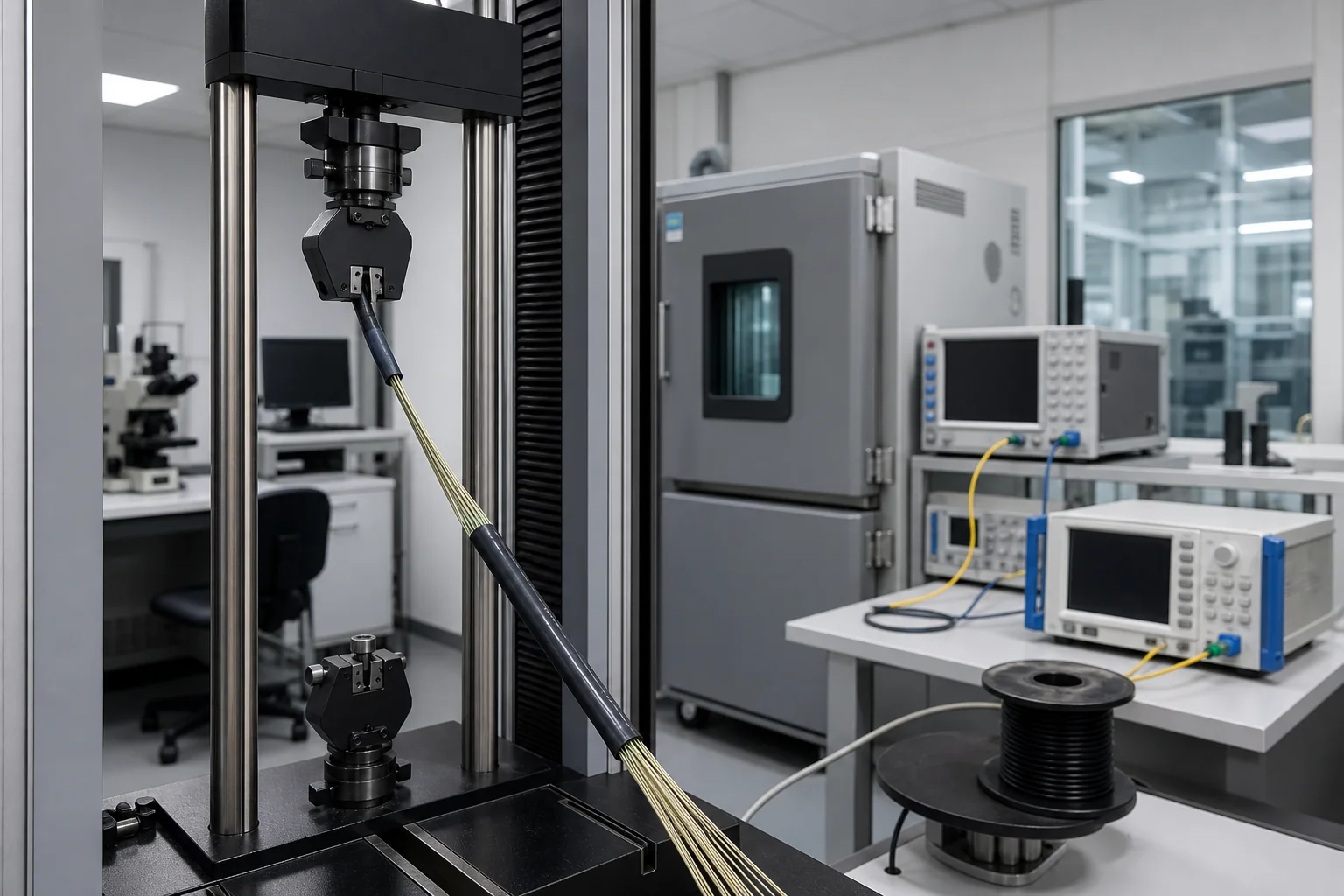
When you specify a fiber optic cable, you are making a series of engineering decisions that directly affect network uptime, signal integrity, and total cost of ownership. The wrong choice can lead to premature failures, costly downtime, or non-compliance with regulatory requirements. This guide explains the key quality parameters, the testing that validates them, and the practical decisions you must make to ensure your network meets both industry norms and your specific application needs.
Essential Terminology and Definitions
Before diving into standards, it is crucial to understand the vocabulary used in cable specifications and test reports. Here are the core terms you will encounter:
- Attenuation: The loss of optical signal power as it travels through the fiber, typically expressed in decibels per kilometer (dB/km). Lower attenuation means better performance over long distances.
- Bandwidth: A measure of the data-carrying capacity of a multimode fiber, often expressed in MHz·km. It indicates how much information can be transmitted over a given length.
- Chromatic dispersion: The spreading of light pulses due to different wavelengths traveling at slightly different speeds, which can limit high-speed transmission.
- Insertion loss: The loss of light at a connection point, such as a splice or connector, measured in decibels (dB).
- Return loss: The amount of light reflected back toward the source, also measured in dB. Higher return loss is better, as reflections can interfere with laser sources.
- Numerical aperture (NA): A dimensionless number that characterizes the range of angles at which the fiber can accept and transmit light. It affects coupling efficiency.
- Proof stress: The tensile stress applied to a fiber during manufacturing to ensure it meets minimum strength requirements. It is typically expressed in gigapascals (GPa) or kpsi.
- Microbending and macrobending: Small-scale or large-scale bends in the fiber that cause additional attenuation. Standards specify minimum bend radii to limit these effects.
These terms appear in every cable datasheet and test report. Familiarity with them allows you to compare products from different manufacturers and to interpret factory test results accurately.
The Role of Cable Quality in Network Performance
Fiber optic cables are the physical medium that carries data, and their quality directly influences the performance of the entire network. Poor-quality cables can introduce excessive attenuation, leading to weak signals that require more amplifiers or repeaters, increasing cost and complexity. They can also suffer from higher dispersion, limiting the bandwidth-distance product and restricting the data rates you can achieve.
In addition to optical performance, mechanical quality is critical. Cables must withstand installation stresses, environmental temperature changes, and potential rodent or moisture damage. Standards define minimum crush resistance, impact resistance, and tensile strength to ensure that cables survive the rigors of deployment and operation. For example, a cable installed in an underground duct may need a higher crush rating than one in a riser space.
Moreover, cable quality affects long-term reliability. Factors like water penetration, hydrogen darkening, and aging of materials can degrade performance over time. Standards include tests that simulate long-term exposure to moisture and temperature to predict the cable’s lifespan. Choosing a cable that meets or exceeds these standards ensures that your network remains stable for its intended service life, typically 20 years or more.
Key Engineering Decisions When Selecting Cables
When you specify a fiber optic cable, you must make several decisions that hinge on quality standards. Here are the most critical ones:
Choosing the Right Fiber Type
The first decision is whether to use single-mode or multimode fiber. Single-mode fiber, with a core diameter of about 9 µm, is designed for long-distance and high-bandwidth applications, while multimode fiber, with core diameters of 50 µm or 62.5 µm, is used for shorter distances, typically within buildings or campuses. Standards such as ITU-T G.652 for single-mode and ISO/IEC 11801 for multimode define the performance categories. Your choice affects attenuation, bandwidth, and cost, so it must align with your network’s reach and data rate requirements.
Selecting the Cable Construction
Cable construction—loose tube, tight buffered, or ribbon—depends on the environment and installation method. Loose tube cables are common for outdoor use due to their resistance to moisture, while tight buffered cables are easier to terminate indoors. Ribbon cables offer high fiber density for high-count applications. Each type has its own set of standards that specify mechanical and environmental performance. For instance, outdoor cables must meet water penetration tests, while indoor cables must comply with fire safety codes like the National Electrical Code (NEC) in the United States.
Specifying Performance Parameters
You must also specify the maximum allowable attenuation and minimum bandwidth for your application. These values are typically defined in the cable standard you reference. For example, a standard single-mode fiber may have a maximum attenuation of 0.4 dB/km at 1310 nm and 0.3 dB/km at 1550 nm, but these are typical values, not universal requirements. Always check the specific standard you are using, as values can vary between different editions and fiber categories.
Interpreting Factory Test Reports
Factory test reports provide evidence that a cable lot meets the specified standards. You need to understand what tests were performed and what the results mean. For instance, a report might list attenuation at several wavelengths, tensile strength, and bend performance. You should verify that the test methods align with the relevant standards and that the results are within the specified limits. If you are unsure, consult the standard or seek expert advice.
Balancing Cost and Performance
Finally, you must balance cost against performance. Higher-quality cables often come with a premium price, but they can reduce installation and maintenance costs over time. For critical infrastructure, the extra investment is usually justified. For less demanding applications, a lower-cost cable that still meets the minimum standards may be sufficient. The key is to define your requirements clearly and then choose a cable that meets them without over-specifying.
In summary, fiber optic cable quality standards are not just technicalities—they are the tools that enable you to make informed decisions. By understanding the terminology, the system role, and the key decisions, you can select cables that will perform reliably and cost-effectively for your network.
Cable Architectures and Their Quality Implications
Fiber optic cables are engineered around three fundamental architectures: loose-tube, tight-buffered, and ribbon. Each architecture addresses different deployment environments and reliability requirements, and each imposes distinct quality control challenges during manufacturing.
Loose-Tube Cables
Loose-tube cables house optical fibers loosely inside gel-filled or dry water-blocking tubes. This design decouples the fiber from mechanical stresses on the cable jacket, making it the preferred choice for outdoor and long-haul installations. The gel or water-blocking material protects against moisture ingress, a leading cause of hydrogen-induced attenuation increase. Quality standards for loose-tube cables emphasize tube fill ratio, buffer tube diameter consistency, and the effectiveness of water-blocking materials.
Tight-Buffered Cables
Tight-buffered cables have a direct coating of thermoplastic buffer around each fiber, providing a robust interface for connectorization and indoor routing. They are commonly used in data centers, enterprise networks, and patch cords. Because the buffer is in direct contact with the fiber, manufacturing tolerances are tighter to avoid microbending losses. Quality control focuses on buffer concentricity, adhesion, and the prevention of fiber strain during bending.
Ribbon Cables
Ribbon cables group fibers into flat arrays, enabling high-density splicing and rapid installation. They are available in both loose-tube and tight-buffered variants. The quality of ribbon cables depends on precise fiber spacing and the uniformity of the matrix material. Standards require that ribbon matrices maintain dimensional stability over temperature extremes, as any deformation can cause macrobending losses.
Comparative Analysis of Cable Architectures
| Attribute | Loose-Tube | Tight-Buffered | Ribbon |
|---|---|---|---|
| Typical deployment | Outdoor, underground, aerial | Indoor, data center, patch cords | High-density trunk, data center |
| Fiber protection | Excellent (stress decoupled) | Good (direct buffer) | Good (matrix encapsulation) |
| Water blocking | Gel or dry tape | Not typically required | Optional (loose-tube ribbon) |
| Splice density | Low to medium | Low | High (mass fusion) |
| Bend sensitivity | Low | Moderate (microbending risk) | Low to moderate |
| Installation complexity | Moderate | Simple | High (requires special tools) |
| Typical fiber count | Up to 288 | Up to 24 | Up to 3456 |
| Key quality metrics | Water penetration, tube fill | Buffer concentricity, adhesion | Matrix uniformity, dimensional stability |
Selecting the Right Architecture for Quality Assurance
Choosing the appropriate cable architecture is a critical step in meeting fiber optic cable quality standards. The decision should be based on the installation environment, required fiber count, and future maintenance strategy.
Environmental Exposure
For outdoor installations where moisture, temperature cycling, and mechanical stress are prevalent, loose-tube cables are the industry standard. Their design inherently protects fibers from axial strain and water ingress, aligning with the environmental requirements of standards such as Telcordia GR-20. In contrast, tight-buffered cables are suitable for indoor environments where flammability and bend radius are more critical than water resistance.
Fiber Count and Density
When high fiber counts are needed, ribbon cables offer the highest packing density and fastest splicing times. However, they require specialized fusion splicers and careful handling to maintain quality. For lower counts, loose-tube or tight-buffered cables are more cost-effective and simpler to terminate.
Maintenance and Repair
Loose-tube cables allow individual buffer tubes to be accessed without disturbing other fibers, simplifying mid-span access. Tight-buffered cables are easier to connectorize directly but may require more careful strain relief. Ribbon cables, while offering high density, can be challenging to repair in the field, as individual fiber access is limited.
Performance Limits and Design Tradeoffs
Every cable architecture has inherent performance limits that engineers must balance against cost and installation requirements. Understanding these tradeoffs is essential for setting realistic quality specifications.
Attenuation and Bend Loss
Loose-tube cables typically exhibit lower attenuation because the fibers are not subjected to lateral pressure. Tight-buffered cables, however, can suffer from microbending losses if the buffer is not perfectly concentric. Ribbon cables may introduce additional loss due to matrix-induced stress, particularly at low temperatures. Standards specify maximum attenuation values, but actual performance depends on the manufacturing quality and installation practices.
Temperature Range
Loose-tube cables are designed to operate over a wide temperature range, typically from -40°C to +70°C, without significant attenuation change. Tight-buffered cables have a narrower range, often -20°C to +70°C, because the buffer material expands and contracts more than the fiber. Ribbon cables fall between the two, with performance depending on the matrix material. These are typical values; consult the relevant standard for specific requirements.
Mechanical Strength
The tensile strength of a cable is determined by its strength members (e.g., aramid yarn, steel, or fiberglass). Loose-tube cables can incorporate multiple strength members to handle high installation tensions. Tight-buffered cables rely more on the buffer and jacket for strength, which limits their maximum pulling force. Ribbon cables, due to their flat profile, may have different crush resistance and impact performance. Design tradeoffs involve balancing tensile strength with cable diameter and flexibility.
Water Blocking
Water ingress is a major threat to fiber reliability. Loose-tube cables use gel or water-swellable tapes to prevent water migration along the cable. Tight-buffered cables are not typically water-blocked, making them unsuitable for direct burial. Ribbon cables can be designed with water-blocking elements, but this adds cost and complexity. Standards such as IEC 60794-1-22 define water penetration tests, and passing these is a normative requirement for outdoor cables.
Cost vs. Performance
Higher-quality cables with stricter tolerances and better materials command a premium. For example, low-water-peak fibers (e.g., G.652.D) are now standard for most applications, but specialty fibers like bend-insensitive (G.657) may be specified for tight bends. The engineer must decide whether the additional cost is justified by the performance gains. In many cases, a well-installed standard cable outperforms a premium cable with poor installation practices.
In summary, the selection of cable architecture is a tradeoff among environmental robustness, fiber density, installation ease, and cost. By understanding these tradeoffs, engineers can specify cables that meet the required fiber optic cable quality standards without over-engineering the solution.
Planning Calculations: From Link Budget to Cable Choice
Before any fiber optic cable is pulled, the network designer must translate the required transmission distance, data rate, and available optical power into a set of quantitative requirements. These calculations directly influence the fiber optic cable quality standards that the installed plant must meet.
Link Loss Budget
The link loss budget sums all expected optical losses along the path: fiber attenuation, connector losses, splice losses, and any passive components (e.g., splitters, patch panels). The total must be less than the system’s power budget—the difference between transmitter output power and receiver sensitivity. A typical margin of 2–3 dB is added to account for aging, temperature drift, and future maintenance.
For example, a 10 km single-mode link using standard G.652.D fiber might assume 0.4 dB/km attenuation at 1310 nm, giving 4 dB of fiber loss. Adding two connector pairs at 0.5 dB each and three fusion splices at 0.1 dB each yields a total of 5.3 dB. If the system power budget is 10 dB, the design margin is 4.7 dB—acceptable. However, if the route includes multiple patch panels or a higher fiber count, the margin shrinks, and the designer must either choose lower-loss components or reduce the number of connections.
Attenuation Coefficients and Wavelengths
Attenuation coefficients are wavelength-dependent. For single-mode fiber, typical values are around 0.4 dB/km at 1310 nm and 0.2 dB/km at 1550 nm. These are not absolute limits but typical values for modern fibers. The actual performance of the installed cable must be verified by testing, as discussed later.
Dispersion and Bandwidth
For high-speed systems (10 Gb/s and beyond), chromatic dispersion becomes a limiting factor. The designer must calculate the dispersion penalty over the link length. For standard single-mode fiber, dispersion at 1550 nm is typically around 17 ps/(nm·km). For a 10 Gb/s system, the dispersion limit might be around 1600 ps/nm for a given transmitter. This translates to a maximum unamplified distance of roughly 94 km. If the planned link exceeds this, the designer must consider dispersion-compensating fiber or a different modulation format.
These calculations are part of the engineering design, but they do not replace the need for post-installation testing to confirm that the installed cable meets the assumed parameters.
Installation Implications: How Quality Standards Affect Field Practices
The quality of a fiber optic cable is not only about the factory—it is also about how the cable is handled during installation. Even a high-quality cable can be degraded by improper pulling, bending, or environmental exposure.
Pulling Tension and Bend Radius
Every cable has a maximum allowable pulling tension and a minimum bend radius. These are typically specified by the manufacturer and are based on the cable’s design and materials. During installation, the pulling tension must not exceed the rated value, and the bend radius must be maintained, especially at corners and entry points. Exceeding these limits can cause microcracks in the fiber, leading to increased attenuation or premature failure.
For example, a typical loose-tube cable might have a recommended maximum pulling tension of 2700 N (about 600 lbf) and a minimum bend radius of 20 times the cable diameter during installation, and 10 times after installation. These are typical values, not universal standards; always consult the manufacturer’s data sheet.
Environmental Considerations
Outdoor cables must be resistant to moisture, temperature extremes, and UV radiation. The cable’s water-blocking design (e.g., gel-filled or dry water-swellable tape) must be appropriate for the environment. In areas with high rodent activity, armored cables may be required. The installation crew must also be aware of the cable’s temperature rating; some cables become stiff or brittle at low temperatures, affecting handling.
Proper Cable Management
After installation, cables must be properly secured and managed in splice trays, patch panels, and conduits. Excessive slack or tight bends can introduce stress. The use of cable ties should be controlled to avoid crushing the cable. These practices are part of the overall quality assurance process, ensuring that the cable’s performance is not compromised.
Testing and Quality Assurance: Verifying Performance
Testing is the final and most critical step in ensuring that the installed fiber optic cable meets the required quality standards. There are two main types of testing: factory testing and field testing. Factory testing is performed by the manufacturer to certify the cable’s performance before shipment. Field testing is performed after installation to verify that the cable has not been damaged and that the splices and connectors are properly made.
Factory Testing
Manufacturers perform a series of tests on each cable length, including attenuation measurements, mechanical tests, and environmental tests. These tests are often based on industry standards such as those from the International Electrotechnical Commission (IEC) or the Telecommunications Industry Association (TIA). For example, IEC 60794-1-2 defines test methods for optical fiber cables.
Typical factory tests include:
- Attenuation measurement – using an OTDR or a light source and power meter to measure the loss of the entire cable length.
- Mechanical tests – such as tensile strength, crush resistance, and impact resistance.
- Environmental tests – such as temperature cycling and water immersion.
These tests ensure that the cable meets the specified performance limits. However, they do not guarantee that the cable will survive improper installation.
Field Testing
After installation, the cable must be tested to confirm that it has not been damaged and that all connections are within acceptable loss limits. The primary tools are the optical time-domain reflectometer (OTDR) and the light source and power meter (LSPM).
An OTDR provides a graphical trace of the fiber, showing loss events such as splices, connectors, and bends. It can also measure the total attenuation and locate faults. An LSPM measures the end-to-end loss of a link, which is the most direct measure of whether the link meets the link loss budget.
Testing should be performed on every fiber in the cable, not just a sample. This is especially important for high-fiber-count cables, where a single bad fiber can cause a service outage.
Acceptance Criteria
The acceptance criteria for field testing are usually based on the link loss budget and the manufacturer’s specifications. For example, a single-mode connector might have a typical insertion loss of 0.5 dB, but the maximum allowable loss might be 0.75 dB. The test results should be compared to these limits, and any fiber that exceeds the limits should be repaired or replaced.
It is important to note that the link loss budget is a design target, not a standard. The actual loss may be higher or lower depending on the quality of the installation. The goal is to ensure that the installed link meets the system’s requirements, not just to meet a generic number.
Practical Field Examples and Caveats
Real-world installations often reveal issues that are not apparent in theory. Here are a few examples and caveats to keep in mind.
Example 1: Overly Tight Bend Radius
During a campus network installation, a technician pulled a 24-fiber loose-tube cable through a conduit and made a sharp 90-degree turn at a manhole. The cable’s bend radius was reduced to less than the recommended minimum. Subsequent OTDR testing showed a significant loss spike at that location. The cable had to be re-pulled, causing delays and extra cost. This highlights the importance of training installers on bend radius requirements and using proper cable guides.
Example 2: Dirty Connectors
In a data center, a link failure was traced to a dirty connector at a patch panel. The insertion loss was over 2 dB, far above the typical 0.5 dB. Cleaning the connector restored the link. This is a common issue in high-density environments where connectors are frequently handled. Regular cleaning and inspection are essential to maintain quality.
Caveat: OTDR Interpretation
OTDR traces can be misleading. For example, a splice with a negative loss (a gain) can appear as a positive event due to differences in backscatter coefficient between two fibers. Also, the OTDR dead zone can obscure events near the launch point. To avoid misinterpretation, it is recommended to test from both ends and to use an OTDR with appropriate pulse widths and averaging times.
Caveat: Standards vs. Typical Values
When specifying cable quality, it is important to distinguish between normative requirements (must meet) and typical values (informational). For instance, the maximum attenuation for a certain fiber class is specified in standards, but the actual attenuation of a specific cable may be lower. Similarly, mechanical parameters like crush resistance have minimum values, but the manufacturer may provide higher values as typical. Always refer to the relevant standard for mandatory limits.
In summary, careful planning, disciplined installation, and thorough testing are the pillars of a reliable fiber optic network. By adhering to fiber optic cable quality standards and applying practical field knowledge, network operators can ensure long-term performance and minimize costly downtime.
Failure Modes and Common Mistakes
Even when a fiber optic cable meets all factory specifications, improper handling or installation can lead to premature failure. Understanding the most common failure modes helps you avoid costly mistakes and ensures your network performs as designed.
Mechanical Stress and Microbending
Excessive tensile stress during pulling is a leading cause of fiber damage. While cables are designed to withstand specified installation tensions, exceeding these limits can cause immediate fracture or, more insidiously, create microscopic cracks that propagate over time. Microbending—tiny bends that cause light to leak from the core—often results from improper cable routing or overtightened cable ties. These bends may not show up in a simple continuity test but can significantly increase attenuation, especially at longer wavelengths.
Environmental and Chemical Exposure
Outdoor cables are protected by jackets and water-blocking materials, but they are not impervious to all conditions. Exposure to certain chemicals, such as solvents or oils, can degrade the jacket, compromising the cable’s integrity. In rodent-prone areas, inadequate armor or protective conduit can lead to chewed cables and service interruptions. Even indoor cables can suffer if installed in areas with extreme temperature fluctuations or high humidity without proper sealing.
Connector and Splice Defects
Poorly terminated connectors or fusion splices are a frequent source of failures. Dirty or scratched connector end faces cause high insertion loss and back reflection, which can disrupt signal transmission. Inaccurate fiber alignment during splicing—due to improper cleaving or faulty equipment—leads to excessive loss and potential reflections. These issues are often preventable with proper training and adherence to manufacturer guidelines.
Procurement Checklist: What to Verify Before You Buy
Selecting the right cable is the first step toward a reliable network. Use this checklist to ensure you are purchasing a product that meets your needs and complies with relevant standards.
- Standards Compliance: Verify that the cable is manufactured and tested in accordance with recognized standards, such as those from the International Electrotechnical Commission (IEC) or the Telecommunication Industry Association (TIA). These standards define performance criteria and test methods.
- Specification Review: Check the datasheet for attenuation coefficients, bandwidth, and mechanical characteristics. Ensure these values meet your link design requirements, not just the minimum standards.
- Test Reports: Request and review the factory test reports. These should include attenuation measurements for each fiber, as well as results from mechanical and environmental tests. Look for consistency with the stated specifications.
- Jacket and Strength Members: Confirm the jacket material is appropriate for the installation environment (e.g., LSZH for plenum spaces, PE for outdoor). Check that strength members are sufficient for the expected pulling tension.
- Traceability: Ensure each reel is labeled with a unique identifier, cable length, and manufacturing date. This aids in quality tracking and future maintenance.
- Warranty and Support: Understand the manufacturer’s warranty terms and what support is available if issues arise.
Lifecycle Maintenance: Ensuring Long-Term Performance
Fiber optic cables are designed for long service life, but they require periodic inspection and maintenance to sustain performance. A proactive approach can prevent unexpected failures and extend the network’s lifespan.
Regular Inspection and Testing
Schedule routine inspections of cables, connectors, and splice enclosures. Use an OTDR to measure attenuation and identify any changes from baseline values. Inspect connector end faces with a scope and clean them as needed. Document all test results to track performance trends over time.
Environmental Monitoring
For outdoor installations, monitor the cable path for potential hazards, such as construction activity, vegetation growth, or water accumulation. Ensure that conduit and manholes remain sealed and free of debris. In indoor environments, check that cables are not subjected to excessive heat or physical stress from new equipment or furniture placement.
Documentation and Records
Maintain accurate records of cable routes, splice locations, and test results. This information is invaluable for troubleshooting and planning upgrades. Update documentation whenever changes are made to the network.
Actionable Recommendations and Conclusion
To ensure your fiber optic network delivers reliable performance throughout its lifecycle, follow these key recommendations:
- Adhere to Standards: Always install and test according to applicable standards. These are not just bureaucratic requirements; they represent best practices distilled from industry experience.
- Invest in Training: Ensure that all personnel involved in installation, splicing, and testing are properly trained and certified. Human error remains the most common cause of cable failures.
- Use Quality Components: Do not compromise on connectors, patch panels, and other hardware. Inexpensive components can undermine the performance of even the best cable.
- Plan for Future Needs: When designing your network, consider future bandwidth requirements. Installing higher-grade cable now can save significant costs later.
- Implement a Maintenance Program: Regular testing and inspection are not optional; they are essential for early detection of problems. Schedule these activities and stick to the plan.
In conclusion, understanding fiber optic cable quality standards is not merely about passing factory tests—it is about ensuring long-term reliability. By avoiding common mistakes, making informed procurement decisions, and committing to lifecycle maintenance, you can build a network that performs optimally for years to come. Remember that standards define the minimum acceptable performance, but your engineering judgment and attention to detail determine the actual quality of your installation.
Frequently Asked Questions
What are the main fiber optic cable quality standards?
Key standards include ITU-T G.652 for single-mode fiber, IEC 60793 for optical fiber, and Telcordia GR-20 for optical fiber cables. These define performance and testing requirements.
What factory tests are performed on fiber optic cables?
Typical factory tests include dimensional checks, tensile strength, bend testing, temperature cycling, and optical measurements like attenuation and return loss.
How is fiber optic cable attenuation measured?
Attenuation is measured using an optical time-domain reflectometer (OTDR) or a light source and power meter, following methods like the cutback or insertion loss technique.
What is the significance of tensile strength testing?
Tensile testing ensures the cable can withstand installation and environmental stresses without damaging the fibers, verifying compliance with specified minimum breaking loads.
Why is environmental testing important for fiber optic cables?
Environmental tests simulate temperature and humidity extremes to ensure the cable maintains optical performance and mechanical integrity over its service life.
What is return loss and why does it matter?
Return loss measures reflected light in the fiber; high return loss (low reflectance) is critical for high-speed and analog systems to prevent signal degradation.
How do quality standards affect cable selection?
Choosing cables that meet recognized standards ensures consistent performance, reliability, and compatibility with network equipment, reducing the risk of failures.
Related In-Depth Guides
Continue with these focused engineering guides:







