
When choosing optical fiber for a network, the fundamental decision is between single mode and multimode fiber. In short, single mode fiber uses a narrow core and a single light path, enabling transmission over long distances with lower attenuation, while multimode fiber uses a larger core and multiple light paths, suited for shorter distances and lower-cost transceivers. The right choice depends on your distance, bandwidth, and budget requirements.
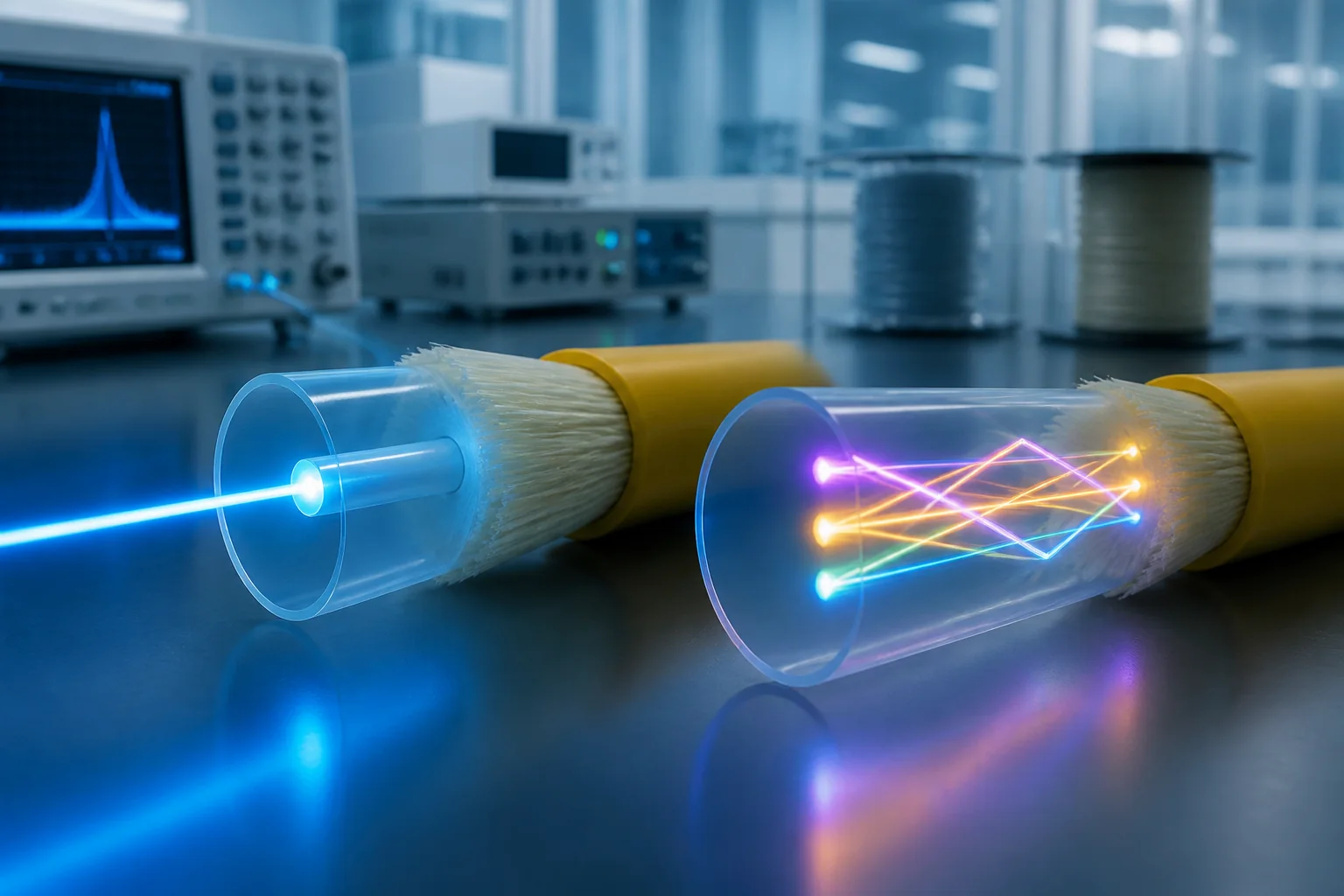
Essential Definitions: Core, Cladding, and Mode
To understand the difference, you need to know three basic terms: core, cladding, and mode.
- Core: The central glass or plastic region through which light travels.
- Cladding: The surrounding layer with a lower refractive index that confines light within the core.
- Mode: A distinct path that light can take as it propagates through the fiber.
In single mode fiber, the core is very small (typically around 9 micrometers in diameter) and the fiber is designed to support only one mode of light propagation. This eliminates modal dispersion—the spreading of light pulses due to different path lengths—which is the primary limitation of multimode fiber.
In multimode fiber, the core is larger (usually 50 or 62.5 micrometers) and supports many modes. Each mode travels a slightly different path, causing light pulses to spread over distance. This modal dispersion limits the effective bandwidth and distance of multimode links.
The Role of Fiber in a Network System
Fiber optic cable is the physical medium that carries data as light pulses between transceivers. It is part of a larger system that includes transmitters (lasers or LEDs), receivers, connectors, and other components. The choice of fiber affects the entire link design:
- Transceiver type: Single mode fiber typically uses laser-based transceivers (e.g., SFP, SFP+ for 1G/10G) that operate at wavelengths like 1310 nm or 1550 nm. Multimode fiber uses VCSELs (vertical-cavity surface-emitting lasers) or LEDs at 850 nm or 1300 nm.
- Distance and bandwidth: Single mode supports much longer distances (tens of kilometers) and higher bandwidths, while multimode is limited to a few hundred meters at high data rates.
- Cost: Multimode transceivers are generally less expensive than single mode ones, but the fiber itself may be slightly cheaper for single mode due to lower material costs.
Engineers must consider the entire link, not just the cable, because the fiber and transceiver must be compatible.
Transceiver Compatibility
Transceivers are designed for specific fiber types. For example, a 10GBASE-SR module is for multimode fiber, while 10GBASE-LR is for single mode. Using the wrong combination will result in excessive loss or no link at all. Always check the transceiver specifications against the fiber type.
Connectors and Splices
Connectors and splices must match the fiber type. Common connectors like LC, SC, and ST are available for both, but the ferrule size and polishing may differ. Splicing single mode fiber requires more precise alignment due to the smaller core, but fusion splicers handle both types.
Key Engineering Decisions When Choosing Between Single Mode and Multimode
Selecting the right fiber involves several decisions that affect performance, cost, and future-proofing.
Distance and Bandwidth Requirements
Determine the maximum link distance and required data rate. For links under 300 meters (typical for data center cabling), multimode fiber can support 100G using parallel optics. For longer distances, single mode is the only viable option. Consider future upgrades: single mode can handle higher rates over longer distances without changing the cable.
Budget and Cost Considerations
Multimode transceivers are cheaper, making it attractive for short-reach applications. However, single mode fiber is often less expensive per meter than multimode, and the cost difference in transceivers is narrowing with new technologies. Calculate total cost of ownership, including installation, testing, and future upgrades.
Installation and Testing
Single mode fiber requires more precise handling during splicing and connectorization. Testing with an OTDR (optical time-domain reflectometer) is similar, but launch conditions differ. Ensure your team is trained for the chosen fiber type.
Future-Proofing
If you anticipate needing higher bandwidth or longer distances in the future, single mode is the safer choice. Many organizations are deploying single mode in data centers to support 400G and beyond, even for short links, to avoid re-cabling.
In summary, the decision between single mode and multimode fiber is not just about the cable—it is about the entire system. Evaluate your current needs and future growth, and you will make an informed choice.
Fiber Optic Network Architectures: Where Each Fiber Type Fits
Beyond the fiber itself, the architecture of the network determines how single mode and multimode fibers are deployed. The two dominant architectures are point-to-point and passive optical networks (PON). In point-to-point links, each transmitter-receiver pair has a dedicated fiber, which is common in data center interconnects and campus backbones. PONs, typical in access networks, use a single fiber shared among many subscribers via optical splitters. Single mode fiber is almost exclusively used in PONs because of its long reach and high bandwidth, while multimode fiber is rarely used in PONs due to distance limitations.
Data Center and Enterprise Cabling
In data centers, the choice between single mode and multimode fiber often comes down to the reach required within the facility. Multimode fiber (OM3/OM4/OM5) is popular for short reaches (up to 100–150 m for 100G Ethernet) because it supports lower-cost transceivers using vertical-cavity surface-emitting lasers (VCSELs). Single mode fiber is used for longer interconnects, such as between buildings or across a campus, where distances exceed 500 m. Modern data centers also use single mode fiber for emerging 400G and 800G links, as multimode transceivers for those speeds are not yet cost-effective.
Telecommunications and Access Networks
Telecommunication networks, including fiber-to-the-home (FTTH) and long-haul backbones, rely almost exclusively on single mode fiber. The reasons are simple: single mode fiber offers virtually unlimited bandwidth-distance product, and the cost of the fiber itself is lower than multimode fiber in large volumes. Access networks using PON architectures (e.g., GPON, EPON) operate over single mode fiber with split ratios up to 1:64 and distances up to 20 km. Multimode fiber is not used in these applications because its modal dispersion limits reach to a few hundred meters.
Single Mode vs Multimode Fiber: Side-by-Side Comparison
The table below summarizes the key differences between single mode and multimode fiber. Note that values are typical engineering values, not normative requirements unless indicated.
| Parameter | Single Mode Fiber (OS1/OS2) | Multimode Fiber (OM3/OM4/OM5) |
|---|---|---|
| Core diameter | 9 µm (typical) | 50 µm (OM3–OM5) or 62.5 µm (OM1/OM2) |
| Cladding diameter | 125 µm | 125 µm |
| Wavelengths used | 1310 nm, 1550 nm (also 1490 nm, 1625 nm for PON) | 850 nm, 1300 nm (VCSELs at 850 nm) |
| Typical reach (10G Ethernet) | Up to 40 km (OS2) at 1310 nm | OM3: 300 m; OM4: 400 m; OM5: 550 m at 850 nm (typical) |
| Bandwidth-distance product | Effectively unlimited (limited by dispersion at very high speeds) | OM4: 4700 MHz·km (effective modal bandwidth at 850 nm) |
| Transceiver cost | Higher (laser sources like FP/DFB) | Lower (VCSELs) |
| Fiber cost | Lower per meter (high volume) | Higher per meter (larger core, tighter tolerances) |
| Installation complexity | More sensitive to connector contamination and bending | More forgiving of alignment due to larger core |
| Typical applications | Telecom, FTTH, long-haul, data center interconnects >500 m | Data center intra-building, LAN backbones, short links |
Selection Criteria: How to Choose Between Single Mode and Multimode
When deciding between single mode and multimode fiber, the primary factors are distance, data rate, and total cost of ownership. For links under 300 m, multimode fiber with VCSEL transceivers is often the most economical choice. For distances beyond 500 m, single mode fiber is the only practical option. However, future-proofing is also critical: if you anticipate upgrading to higher speeds (e.g., 400G or 800G), single mode fiber may be a better long-term investment, even for short reaches, because it can support those speeds with appropriate transceivers.
Distance and Data Rate Requirements
Determine the maximum link length and the required data rate. For 10G Ethernet, OM4 multimode supports up to 400 m, while single mode OS2 supports 40 km. For 100G Ethernet, OM4 supports 100 m (using parallel optics) or 150 m (using PAM4), whereas single mode supports 2 km or more. If your link exceeds the multimode reach, you must use single mode.
Budget and Cost Analysis
Perform a total cost analysis that includes fiber, transceivers, installation, and maintenance. Multimode fiber costs more per meter but transceivers are cheaper. For short links, the transceiver savings often outweigh the fiber cost. For long links, single mode fiber is cheaper per meter and the only viable option. Also consider that single mode transceivers are becoming more cost-competitive as volumes increase.
Future-Proofing and Scalability
Single mode fiber is widely considered more future-proof because it supports higher data rates over longer distances without changing the fiber. Multimode fiber may require upgrading to a higher OM category (e.g., OM3 to OM4) to support higher speeds, which is costly. If you expect to grow beyond 100G, single mode is the safer choice.
Performance Limits and Design Tradeoffs
Both fiber types have inherent performance limits that influence network design. For multimode fiber, the main limit is modal dispersion, which causes pulse spreading and limits bandwidth-distance product. This is mitigated by using laser-optimized fiber (OM3/OM4/OM5) and VCSELs that launch light into a limited number of modes. For single mode fiber, chromatic dispersion and nonlinear effects become significant at very high data rates (e.g., 100G and beyond) over long distances, but these are managed with dispersion compensation and advanced modulation formats.
Modal Dispersion in Multimode Fiber
Modal dispersion occurs because different modes travel at different speeds, causing the optical pulse to broaden. The effective modal bandwidth (EMB) is a key parameter that defines the maximum data rate for a given distance. For example, OM4 has an EMB of 4700 MHz·km at 850 nm, meaning a 10G signal can travel 400 m (since 10 GHz × 0.4 km = 4 GHz·km, within the EMB). Exceeding this limit results in excessive bit error rates.
Chromatic Dispersion in Single Mode Fiber
Chromatic dispersion is the broadening of pulses due to different wavelengths traveling at different speeds. Standard single mode fiber (G.652) has zero dispersion around 1310 nm and about 17 ps/(nm·km) at 1550 nm. For 10G links up to 40 km, this is not a major issue, but for 100G and beyond, dispersion compensation or coherent detection is required. Design tradeoffs include choosing the operating wavelength (1310 nm for zero dispersion, 1550 nm for lower attenuation) and using dispersion-shifted fiber for long-haul systems.
Design Tradeoffs: Attenuation, Cost, and Reliability
Single mode fiber has lower attenuation (typically 0.2 dB/km at 1550 nm) compared to multimode (typically 2.5 dB/km at 850 nm), which is why it is preferred for long distances. However, single mode systems require more precise connectors and splicing, increasing installation cost. Multimode systems are more tolerant of misalignment, reducing installation time and cost. Reliability is similar for both, but single mode is less susceptible to modal noise and is more stable over temperature variations.
In summary, the choice between single mode and multimode fiber is not just about the fiber itself, but about the entire system architecture, including transceivers, connectors, and future upgrade paths. By carefully evaluating distance, data rate, budget, and scalability, you can select the fiber type that best meets your current and future needs.
Planning Calculations: From Link Length to Optical Budget
Before choosing between single mode and multimode fiber, you must calculate the optical link budget. This is a fundamental engineering step that determines whether the proposed link will operate reliably over its lifetime. The link budget is the difference between the transmitter output power and the receiver sensitivity, expressed in decibels (dB). The total link loss must be less than this budget, with a safety margin for connector degradation, splices, and aging.
Step-by-Step Link Budget Calculation
- Determine the required distance – Measure the actual cable route, including vertical risers, horizontal runs, and patch cords. Add a 10% contingency for routing changes.
- Select the transceiver type – Choose the optical interface (e.g., 10GBASE-SR for multimode, 10GBASE-LR for single mode) and note its typical transmit power and receiver sensitivity. These are defined in the IEEE 802.3 standard and are normative.
- Calculate the channel insertion loss – Sum the attenuation of the fiber (typical values: 3.5 dB/km for OM3/OM4 at 850 nm, 0.4 dB/km for OS2 at 1310 nm), connector losses (typical 0.5 dB per mated pair, but high-quality connectors can be 0.3 dB), and splice losses (typical 0.1–0.2 dB per fusion splice).
- Add a system margin – Industry practice is to include at least 2–3 dB of margin to account for temperature variations, connector contamination, and future splices. This is not a standard requirement but a recommended engineering practice.
For example, a 300-meter multimode link using OM4 fiber at 850 nm would have a fiber loss of about 1.05 dB (300 m × 3.5 dB/km). Adding two connector pairs (1.0 dB) and a 2 dB margin gives a total of 4.05 dB. A typical 10GBASE-SR transceiver has a link budget of around 8 dB, so the link is feasible. In contrast, a 10 km single mode link at 1310 nm would have a fiber loss of 4 dB (10 km × 0.4 dB/km), plus connectors and margin, totaling about 7 dB, which is within the typical 10GBASE-LR budget of 12 dB.
Caveat: Always use the worst-case values from the transceiver datasheet, not typical values, for a reliable design. Also, verify the actual fiber attenuation with an OTDR after installation.
Installation Implications: Physical Differences That Matter
The physical characteristics of single mode and multimode fiber affect installation practices, termination methods, and testing procedures.
Core Size and Connector Alignment
Single mode fiber has a 9 µm core, while multimode fiber typically has 50 µm (OM2–OM5) or 62.5 µm (OM1) cores. The smaller core of single mode fiber requires tighter connector alignment tolerances. This means that single mode connectors, such as LC or SC, must be of higher precision. In practice, this translates to more careful polishing and inspection. Multimode connectors are slightly more forgiving, but contamination is still a major issue for both types.
Cleaning and Inspection
Both fiber types are susceptible to dust and oil contamination on connector end faces. However, single mode connectors are more sensitive because the light is concentrated in a very small area. A single dust particle can cause significant back reflection and insertion loss. Therefore, always clean and inspect connectors before mating. Use a scope with at least 200× magnification to verify that the end face is free of scratches and contamination.
Splicing and Termination
Fusion splicing is common for both types, but single mode fibers require more precise alignment due to the small core. Modern fusion splicers handle this automatically, but the operator must ensure that the fiber ends are cleaved cleanly. Mechanical splicing is also possible, but fusion splicing is preferred for lower loss and higher reliability.
For termination, field-installable connectors are available for both types, but single mode versions are more sensitive to end face geometry. Pre-terminated patch cords and trunk cables are recommended for high-density data center environments to minimize installation time and testing effort.
Bend Radius and Cable Management
Both fiber types have minimum bend radius specifications, but single mode fiber is more sensitive to macrobending if the bend radius is too small. This is because the light in the small core can leak into the cladding when bent. For indoor installations, a typical minimum bend radius is 10 mm for bend-insensitive single mode fiber and 7.5 mm for multimode, but always follow the manufacturer’s specifications.
Testing and Quality Assurance: Verifying the Link
After installation, you must test the fiber link to ensure it meets the design requirements. This is a critical step that is often overlooked, leading to intermittent failures and costly troubleshooting.
Insertion Loss Testing
The most common test is insertion loss measurement using a light source and power meter (LSPM). You measure the power at the transmitter and receiver ends and calculate the loss. This test is performed at the operating wavelength (e.g., 850 nm for multimode, 1310 nm or 1550 nm for single mode). The measured loss must be less than the calculated link loss budget. This is a normative requirement in standards such as TIA-568 and ISO/IEC 11801.
OTDR Testing
An Optical Time Domain Reflectometer (OTDR) provides a detailed profile of the fiber, showing the loss of each splice, connector, and the overall attenuation. It is used to locate faults and verify that the fiber is not damaged. OTDR testing is essential for outside plant (OSP) installations but is also recommended for long indoor runs. The OTDR trace can be used to compare the actual loss with the expected values.
End Face Inspection
Before testing, inspect all connector end faces with a fiber optic microscope. This is a mandatory step in most quality assurance procedures. Contamination is the leading cause of link failure, and a simple inspection can prevent many issues.
Polarization Mode Dispersion (PMD) Testing
For high-speed single mode links (e.g., 40G and 100G), PMD can be a concern. PMD is a random effect caused by fiber asymmetry and can cause pulse broadening. Testing PMD is typically done with specialized equipment and is only necessary for very long links or when specified by the customer. For most enterprise links, it is not required.
Practical Field Example
Consider a data center upgrade where you are connecting two switches 150 meters apart. You decide to use multimode OM4 fiber because the distance is well within its 400-meter reach for 40GBASE-SR4. After installation, you perform an insertion loss test and measure 1.8 dB loss, which is within the 2.5 dB budget. You also use an OTDR to verify that there are no bad splices. The link passes, and you are confident it will support the required data rate.
However, if you had chosen single mode fiber for the same distance, you would need to ensure that the connectors are clean and that the fusion splices are low-loss. The testing procedure would be similar, but the OTDR would show a much lower attenuation per kilometer, which is expected.
Caveats and Common Pitfalls
- Don’t mix fiber types – Never connect single mode transceivers to multimode fiber or vice versa, as this can cause high loss and damage to optics.
- Beware of mode conditioning patch cords – For legacy multimode links with 10GBASE-LRM, mode conditioning patch cords are required, but they are not needed for modern OM3/OM4 links.
- Always test after termination – Even pre-terminated cables should be tested after installation to ensure no damage occurred during pulling.
- Document everything – Keep records of test results, connector types, and fiber lengths for future troubleshooting and upgrades.
In summary, proper planning calculations, careful installation, and thorough testing are essential to ensure that your single mode vs multimode fiber choice performs as expected. By following these practices, you can avoid costly rework and downtime.
Failure Modes and Common Mistakes in Single Mode vs Multimode Fiber Systems
Even with careful planning, field deployments often reveal issues that shorten link life or degrade performance. Understanding typical failure modes helps you avoid them—especially when choosing between single mode vs multimode fiber for a given application.
Mismatched Components and Connector Types
One of the most frequent mistakes is mixing single mode and multimode components in the same link. While a single mode transceiver plugged into a multimode patch cord may work over short distances, the reverse—multimode transceiver on single mode fiber—usually fails due to high attenuation. Similarly, using a single mode patch cord on a multimode link can cause severe loss at the connector interface because the smaller core diameter of single mode fiber does not align with the larger multimode core.
Another common error is using UPC (ultra-polished) connectors with APC (angled-polished) connectors. The physical contact geometry differs, leading to air gaps and high return loss. Always verify connector polish type before mating.
Incorrect Transceiver Wavelength
Multimode systems typically use 850 nm or 1300 nm, while single mode systems use 1310 nm or 1550 nm. Installing a 1300 nm multimode transceiver on a link designed for 850 nm will not work because the fiber’s modal bandwidth is optimized for 850 nm. Conversely, using a single mode transceiver on multimode fiber may work over short distances but is not a reliable long-term solution.
Poor Bend Radius and Cable Stress
Exceeding the minimum bend radius—especially during installation—can cause micro-bends that increase attenuation permanently. For tight spaces, use bend-insensitive fiber, but always respect the manufacturer’s specified bend limits. Never pull cables beyond their rated tensile strength.
Contamination and End Face Damage
Dust, oil, or debris on connector end faces is the leading cause of intermittent failures. Even microscopic particles can cause back reflection and insertion loss. Always clean connectors before mating and use dust caps when not in use.
Documentation and Labeling Errors
In complex networks, mislabeling fiber runs can lead to costly troubleshooting. Use consistent labeling conventions and maintain accurate as-built documentation.
Procurement Checklist for Single Mode vs Multimode Fiber
Before purchasing fiber, cable, or transceivers, use this checklist to ensure you select the right type and avoid costly mistakes.
- Define link length and data rate: For runs under 300 meters, multimode is often sufficient and more cost-effective. For longer distances or future scalability, single mode is the better choice.
- Determine transceiver type: Choose transceivers that match your fiber type and required reach. Verify wavelength and connector type (LC, SC, etc.).
- Check connector polish: Ensure all connectors and adapters use the same polish (UPC or APC).
- Specify fiber grade: For multimode, select OM3, OM4, or OM5 based on needed bandwidth and distance. For single mode, OS2 is standard for outdoor and long-haul.
- Consider cable construction: Indoor vs. outdoor, tight-buffer vs. loose-tube, and armoring requirements.
- Verify bend radius specifications: Choose bend-insensitive fiber if you anticipate tight bends.
- Plan for testing: Include budget for an OTDR, power meter, and light source, or hire a certified contractor.
- Check compatibility: Ensure patch cords, pigtails, and adapters match your fiber type and connector style.
Lifecycle Maintenance and Best Practices
Proper maintenance extends the life of your fiber network and prevents downtime. While standards like TIA-568 and ISO/IEC 11801 define installation and testing requirements, maintenance practices are often based on industry best practices.
Regular Inspection and Cleaning
Inspect connector end faces with a microscope before every mating. Clean with appropriate tools—dry cleaning is preferred, but if wet cleaning is needed, use approved solvents. Always re-inspect after cleaning.
Environmental Monitoring
For outdoor cables, monitor for moisture ingress, rodent damage, and physical stress. Indoor cables should be protected from excessive heat or cold, though typical office environments are within safe ranges.
Periodic Testing
Run OTDR traces annually or after any major network change to detect fiber degradation. Power meter tests can verify link loss against the original budget.
Documentation Updates
Keep records of test results, splice locations, and any repairs. This helps in troubleshooting and planning future upgrades.
Actionable Recommendations and Conclusion
Choosing between single mode and multimode fiber is not a one-size-fits-all decision. Here are practical guidelines to help you move forward.
When to Choose Multimode Fiber
Multimode is ideal for short-distance applications within a data center, campus backbone, or building riser. It is generally lower cost for transceivers and connectors, and easier to terminate. If your link lengths are under 300 meters and data rates are 100 Gbps or less, multimode is a strong candidate.
When to Choose Single Mode Fiber
Single mode is the clear winner for distances beyond 300 meters, for outdoor runs, and for future-proofing to higher data rates. It supports longer reach and higher bandwidth, but transceivers are more expensive. For long-haul or metro networks, single mode is the only practical option.
Future-Proofing Considerations
If you anticipate growth in data rates or link lengths, single mode offers more headroom. However, multimode (especially OM5) can support multiple wavelengths with shortwave wavelength division multiplexing (SWDM), extending its usefulness.
Final Thoughts
The key to a successful fiber deployment is understanding your specific requirements—distance, data rate, environment, and budget. Avoid the common mistakes of mismatched components and poor installation practices. Use the procurement checklist to guide your purchases, and implement a lifecycle maintenance plan to ensure long-term reliability.
In summary, the single mode vs multimode fiber decision hinges on distance, cost, and scalability. By following the recommendations in this guide, you can make an informed choice that meets your current needs and prepares you for the future.
Frequently Asked Questions
What is the main difference between single mode and multimode fiber?
Single mode fiber has a small core (about 9 µm) that allows only one light mode, enabling long-distance transmission (up to 40+ km) with lower attenuation. Multimode fiber has a larger core (50 or 62.5 µm) that supports multiple modes, suitable for shorter distances (up to 550 m for 10G) due to modal dispersion. Choose based on distance and bandwidth needs.
Can I connect single mode fiber to multimode fiber?
Directly connecting them is not recommended because of core size mismatch, causing high loss. However, you can use mode conditioning patch cords or media converters to interface them, but this adds cost and complexity. For new installations, stick to one type to avoid compatibility issues.
How do I choose between single mode and multimode fiber for my data center?
Consider distance, bandwidth, and cost. For runs under 300-500 meters, multimode (OM4/OM5) with VCSEL lasers is cost-effective. For longer distances or future-proofing beyond 400G, single mode is better. Also, check the optics you plan to use; single mode requires more expensive lasers but offers longer reach.
What are the typical testing standards for single mode and multimode fiber?
Testing typically follows TIA/EIA standards: for multimode, use an OTDR with a launch cable and measure at 850 nm; for single mode, test at 1310 nm and 1550 nm. Ensure connectors are clean and use reference test cords. Certification requires meeting loss budgets per TIA-568.3-D, but always follow project specifications.
Can I use single mode transceivers on multimode fiber and vice versa?
No, transceivers are designed for specific fiber types. Single mode transceivers (e.g., LX) use a narrow laser and expect a 9 µm core; using them on multimode fiber will cause high loss and unreliable links. Conversely, multimode transceivers (e.g., SR) use VCSELs and won't couple efficiently into single mode fiber. Always match transceiver type to fiber type.
Is single mode fiber more expensive than multimode fiber?
The fiber cable itself is often cheaper for single mode, but the optics (lasers) are more expensive. Multimode fiber and optics are generally cheaper for short distances. However, single mode offers longer reach and higher bandwidth potential, making it more cost-effective for long-haul or future upgrades. Total cost depends on distance and required data rates.
Related In-Depth Guides
Continue with these focused engineering guides:







