Fiber Optic Cable Types: What You Need to Know First
If you are planning a fiber optic network, the single most important decision you will make is choosing the right fiber optic cable types. This guide cuts through the jargon and gives you a clear, engineering-based framework for selection. In short, fiber optic cables are categorized by their transmission mode (single-mode or multimode), their construction (loose-tube, tight-buffered, ribbon), and their application environment (indoor, outdoor, aerial, buried). The right choice depends on your distance, bandwidth, and installation conditions. Start here to understand the fundamentals, then move through the guide to match a cable to your project.
Essential Definitions and Terminology
Before comparing cable types, you need to master the basic vocabulary. These terms appear throughout specifications and vendor documentation.
Core, Cladding, and Coating
The core is the glass or plastic path that carries light. Around it is the cladding, a layer with a lower refractive index that keeps light inside the core through total internal reflection. The coating is a protective polymer layer applied directly to the cladding; it does not affect light transmission but shields the glass from moisture and mechanical damage.
Single-Mode vs. Multimode Fiber
This is the most fundamental classification. Single-mode fiber has a small core (typically 9 µm) and transmits only one light mode, enabling very long distances and high bandwidth. Multimode fiber has a larger core (50 µm or 62.5 µm) and supports multiple modes, which limits distance due to modal dispersion. For most long-haul and data-center backbone links, single-mode is the standard; for short reach inside buildings, multimode is often more cost-effective.
Loose-Tube and Tight-Buffered
These terms describe how the fiber is protected within the cable. Loose-tube cables have fibers placed loosely in gel-filled tubes, which isolate them from external stress and moisture. They are typical for outdoor use. Tight-buffered cables have a solid buffer coating directly over the fiber, making them more flexible and easier to terminate, but they are less protected from moisture and are usually used indoors.
Other Key Terms
- Attenuation: Signal loss over distance, measured in dB/km.
- Bandwidth: Data-carrying capacity, often expressed in MHz·km for multimode.
- Connector types: Such as LC, SC, and ST, which are not cable types but are critical for compatibility.
- Armored cable: Contains a metal layer for extra protection against rodents or crush.
The Role of Fiber Optic Cables in a Network
Fiber optic cables are the physical medium that carries data as light pulses. They form the backbone of modern telecommunications, data centers, and industrial networks. The cable you choose directly impacts signal integrity, reliability, and installation cost.
Transmission Path
In any fiber link, the cable is the conduit for optical signals. It must maintain low attenuation and minimize reflections to ensure that the signal arrives at the receiver with sufficient power. The cable’s mechanical design protects the fiber from bending, pulling, and environmental stress, which could otherwise cause micro-bends and signal loss.
Environmental Protection
Cables are engineered for specific environments. Outdoor cables must withstand temperature extremes, UV radiation, and moisture ingress. Indoor cables must meet fire safety codes, such as plenum or riser ratings. Aerial cables need strength members to support their own weight, while buried cables require armor or gel to resist water and ground movement.
Impact on Network Performance
The cable type influences the maximum link length and data rate. For example, a multimode OM4 cable can support 100 Gb/s up to 150 meters, while a single-mode OS2 cable can go far beyond that. Choosing the wrong type can lead to excessive attenuation, dispersion, or even physical failure. Therefore, the cable is not just a passive component; it is a critical element of system design.
Key Engineering Decisions You Must Make
Selecting a fiber optic cable involves more than picking a category. You must evaluate several engineering parameters to ensure the cable meets your performance and installation requirements.
1. Transmission Mode and Fiber Class
Decide between single-mode and multimode based on your distance and data rate needs. For distances beyond a few hundred meters, single-mode is usually required. For shorter links, multimode can be more economical. Within each mode, there are classes (e.g., OS1, OS2 for single-mode; OM1–OM5 for multimode) that define performance levels. These classes are standardized by the International Telecommunication Union (ITU) and the International Organization for Standardization (ISO)/IEC. Always verify that your chosen fiber class meets the required performance for your application.
2. Cable Construction and Installation Environment
Consider where the cable will be installed. Outdoor cables often use loose-tube construction with gel filling for water blocking. Indoor cables typically use tight-buffered construction for ease of handling. If the cable will be exposed to harsh conditions, you may need armored or double-sheathed designs. For riser or plenum spaces, you must comply with local fire codes, which dictate the jacket material and flame-retardant properties.
3. Connector and Splicing Requirements
The cable type affects how you terminate it. Tight-buffered cables can be directly connectorized, while loose-tube cables require a breakout kit or a splice to pigtails. This impacts labor time and cost. Also, consider whether you will use fusion splicing or mechanical splicing, as this may influence the cable design.
4. Future-Proofing and Budget
While initial cost is important, think about future bandwidth needs. Single-mode fiber offers greater headroom for higher speeds and longer distances, making it a safer long-term investment. Multimode may be cheaper today but could require replacement sooner. Balance your budget with the expected service life of the network.
By addressing these decisions early, you can narrow down the vast array of fiber optic cable types to a few that are truly suitable for your project. The next sections of this guide will delve into each category in detail, providing specifications and selection criteria.
Major Cable Architectures and Their Tradeoffs
Beyond the fiber itself, the cable architecture determines how the fiber is protected, how it handles environmental stress, and how easily it can be terminated. The three dominant architectures in modern networks are loose-tube, tight-buffered, and ribbon. Each solves a different set of problems, and the right choice depends on your installation environment and maintenance strategy.
Loose-Tube Cables
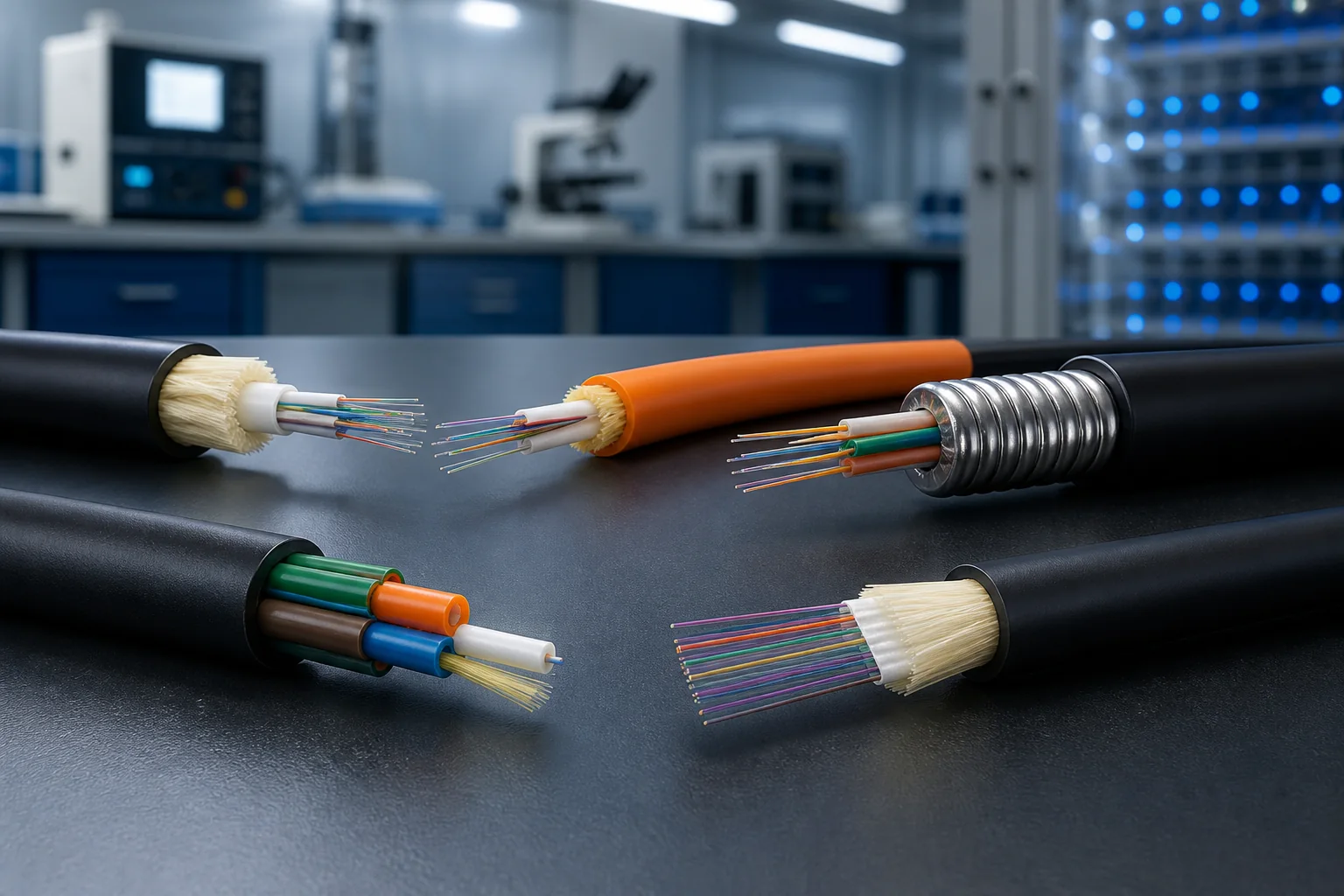
Loose-tube cables house fibers loosely inside gel-filled or dry water-blocking tubes. This design allows the fiber to move independently from the cable jacket, which is critical in outdoor installations where temperature swings cause cable contraction and expansion. The excess fiber length inside the tube prevents stress on the glass, preserving optical performance over wide temperature ranges.
Loose-tube cables are the standard for outside plant (OSP) applications—aerial, duct, and direct-buried. They offer excellent water resistance, especially with gel-filled versions, and can accommodate high fiber counts. However, they require more preparation time for termination because the gel must be cleaned and the fibers are not individually protected.
Tight-Buffered Cables
Tight-buffered cables have a protective coating applied directly over the fiber, eliminating the gel-filled tubes. This makes them easier to handle and terminate—ideal for indoor environments like data centers, enterprise LANs, and patch panels. The buffer provides mechanical protection and allows for direct connectorization without the need for breakout kits.
Because tight-buffered cables are more rigid and less tolerant of temperature extremes, they are typically used indoors or in protected environments. For outdoor runs, they are often used in riser or plenum spaces within buildings, or in short outdoor segments where they are protected by conduit.
Ribbon Cables
Ribbon cables arrange fibers in a flat, parallel array, allowing for mass fusion splicing. This architecture dramatically reduces installation time for high-fiber-count trunk lines. A 12-fiber ribbon can be spliced in one operation, compared to individual splicing for loose-tube or tight-buffered designs.
Ribbon cables are available in both loose-tube and tight-buffered variants. They are common in long-haul networks and data center interconnects where fiber counts exceed 144. The tradeoff is reduced flexibility—ribbon cables have a larger minimum bend radius and are more difficult to route in tight spaces.
Comparison Table: Cable Architectures at a Glance
| Attribute | Loose-Tube | Tight-Buffered | Ribbon |
|---|---|---|---|
| Primary environment | Outdoor (aerial, duct, direct-buried) | Indoor (riser, plenum, patch panels) | Both, but mainly high-fiber-count trunks |
| Water protection | Excellent (gel or dry block) | Good (jacket only) | Varies by jacket type |
| Termination ease | Moderate (requires gel cleanup) | Easy (direct connectorization) | High (mass fusion splicing) |
| Temperature tolerance | Wide range | Narrower range | Similar to loose-tube or tight-buffered |
| Fiber count flexibility | Low to very high (up to 864+) | Low to moderate (typically 2–144) | High (144 to 3456+) |
| Typical cost per fiber | Lower for high counts | Higher for low counts | Lower for very high counts |
Note: The values in this table are typical engineering ranges, not normative requirements. Always consult the manufacturer’s datasheet for specific product limits.
How to Choose the Right Fiber Optic Cable Type
Selecting the correct cable type is a balance of performance, installation environment, and lifecycle cost. Use the following criteria as a decision framework.
1. Assess the Installation Environment
Start with the physical path. Will the cable be exposed to moisture, temperature extremes, or UV radiation? Outdoor installations demand loose-tube construction with water-blocking. Indoor installations can use tight-buffered cables, but you must comply with local fire codes—plenum-rated jackets are required in air-handling spaces, while riser-rated jackets are acceptable in vertical shafts.
2. Determine Fiber Count and Future Growth
Estimate the number of fibers needed today, then multiply by a growth factor of 1.5 to 2 for future capacity. If you anticipate needing more than 144 fibers, ribbon cables become attractive due to reduced splicing time. For lower counts, loose-tube or tight-buffered are more cost-effective.
3. Consider Installation and Maintenance Practices
If your team is trained in fusion splicing, ribbon cables can save days of labor. If you rely on pre-terminated assemblies or field-installable connectors, tight-buffered cables simplify the process. For outdoor runs that may need mid-span access, loose-tube cables allow individual fiber breakout.
4. Evaluate Long-Term Reliability
Loose-tube cables have a proven track record in harsh environments, but they require proper sealing and grounding. Tight-buffered cables are easier to maintain in indoor settings but may not survive outdoor exposure without additional protection. Ribbon cables, while efficient, can be more challenging to repair—a single fiber break may require accessing the entire ribbon.
Performance Limits and Design Tradeoffs
Every cable type has physical limits that affect network performance. Understanding these limits helps you avoid costly redesigns.
Attenuation and Dispersion
Attenuation—the loss of optical power—is influenced by the fiber itself, but cable design can add micro-bending losses if the fiber is subjected to excessive stress. Loose-tube designs minimize this by allowing fiber movement. Tight-buffered cables, with their tighter coupling, can exhibit higher micro-bending sensitivity, especially at lower temperatures.
Dispersion, which broadens optical pulses, is a fiber property, not a cable property. However, the choice of single-mode vs. multimode fiber—which is independent of cable architecture—sets the dispersion limits. For long distances, single-mode fiber is required; for short distances, multimode is often sufficient.
Mechanical Limits
Each cable has a maximum tensile load and minimum bend radius. These are specified by the manufacturer and are critical for installation. Exceeding the bend radius can cause immediate attenuation spikes or permanent fiber damage. Typical minimum bend radii are around 10 times the cable diameter for installation and 15 times for long-term static loads, but these are not universal—always check the datasheet.
Environmental Ratings
Outdoor cables are rated for temperature ranges (e.g., -40°C to +70°C) and may have UV-resistant jackets. Indoor cables have fire ratings (plenum, riser, LSZH) that are mandated by building codes. These ratings are not interchangeable—using an indoor cable outdoors will lead to premature failure, while using an outdoor cable indoors may violate fire safety regulations.
Design Tradeoffs
The key tradeoff is between flexibility and protection. Loose-tube cables offer superior environmental protection but are bulkier and harder to terminate. Tight-buffered cables are easy to handle but are not designed for outdoor exposure. Ribbon cables excel in installation speed but require specialized equipment and are less flexible in routing.
There is no single “best” cable type—only the best fit for your specific application. By weighing these factors against your network’s requirements, you can make an informed decision that balances performance, cost, and reliability.
Planning Calculations: From Link Length to Fiber Count
Before selecting a specific fiber optic cable type, you must translate the network requirement into numbers that drive the cable choice. The two most important calculations are the optical link loss budget and the fiber count. Both influence whether you choose single-mode or multimode, loose-tube or tight-buffered, and how many fibers you need.
Optical Link Loss Budget
The loss budget is a simple sum of all expected losses along the link: connector losses, splice losses, and attenuation per kilometer. The result must be less than the power budget of the transceivers you plan to use. For example, a 10 km single-mode link using standard G.652.D fiber might have an attenuation of about 0.4 dB/km at 1310 nm, plus connector losses of 0.5 dB per pair and splice losses of 0.1 dB per splice. If you have two connector pairs and three splices, the total loss is roughly 4.0 + 1.0 + 0.3 = 5.3 dB. This must be below the receiver sensitivity minus launch power, which is typically 10-20 dB for common SFP modules.
Always add a margin of 2-3 dB for future repairs, aging, and environmental changes. If the calculated loss exceeds the budget, you may need to choose a lower-loss fiber, reduce splice points, or use higher-power optics.
Fiber Count and Growth Planning
Fiber count is often underestimated. A common rule of thumb is to install at least 50% more fibers than currently needed, but this is a typical practice, not a standard. For backbone links, many engineers specify 24, 48, or 72 fibers even if only 6 are used initially, because future upgrades (like adding more wavelengths or splitting to multiple buildings) are cheaper than pulling a new cable.
When calculating fiber count, consider not only active connections but also spare fibers for redundancy, testing, and future services. For example, a campus backbone connecting three buildings might need 12 fibers for current traffic, but a 24-fiber cable provides room for growth without overbuilding.
Installation Implications: Pulling, Bending, and Splicing
The physical installation method determines which cable construction is practical. Aerial, duct, direct burial, and indoor riser each impose different mechanical stresses. The cable jacket, strength members, and allowable bend radius are critical.
Pulling Tension and Bend Radius
During installation, cables are pulled through conduits or along messenger wires. The pulling tension must not exceed the cable’s rated limit, typically 2700 N for a 12-fiber loose-tube cable, but this varies widely. Bend radius is equally important: the minimum bend radius during installation is usually 20 times the cable diameter, while after installation it is 10 times. These are typical values from manufacturer datasheets, not universal standards.
If you are pulling through a conduit with multiple bends, use a cable with a central strength member and aramid yarn, which resists stretching. For long pulls, use a swivel pulling eye and lubricant to reduce friction.
Indoor vs. Outdoor Installation
Outdoor cables must be water-blocked and UV-resistant. Loose-tube cables with gel or dry water-blocking are standard for outdoor use. Indoor cables, such as tight-buffered or distribution cables, have a flame-retardant jacket (e.g., OFNR or OFNP) and are easier to terminate directly to connectors.
If you need to bring outdoor cable into a building, you must transition to an indoor-rated cable at the entry point, using a breakout kit or a patch panel. This avoids exposing indoor spaces to outdoor cable materials that may not meet fire codes.
Splicing and Termination Considerations
Loose-tube cables are typically spliced in splice trays or terminated in patch panels. Tight-buffered cables can be connectorized directly, saving space and time. Ribbon cables allow mass fusion splicing, which is faster for high-fiber-count connections but requires specialized equipment.
Plan for splice closures and patch panels that accommodate the cable type. For example, a loose-tube cable with 12 fibers might use a splice tray that holds 12 fusion splices, while a ribbon cable with 144 fibers might use a mass fusion splice tray.
Testing and Quality Assurance: Verifying Performance
After installation, you must verify that the cable meets specifications. Testing is not optional; it is a standard practice and often required by project contracts. The two main tests are insertion loss and OTDR (Optical Time-Domain Reflectometer) testing.
Insertion Loss Testing
Insertion loss testing measures the total loss of a link using a light source and power meter. It is performed on every fiber after splicing and termination. The measured loss must be within the calculated budget. For example, if your budget allowed 5.3 dB, the measured loss should be below that, ideally with the margin.
Typical insertion loss for a single-mode connector is 0.5 dB, but high-quality connectors can achieve 0.2 dB. These are typical values, not standards. The industry standard for testing is TIA-568 for premises cabling, but for outside plant, you may follow IEC 61280-4-2.
OTDR Testing
OTDR testing provides a graphical trace of the fiber, showing loss events such as splices, connectors, and breaks. It is used to locate faults and verify splice quality. An OTDR can measure the loss of individual splices, which should be below 0.1 dB for fusion splices, but this is a typical value, not a strict limit.
OTDR testing is also used to document the installation. You should save the trace files as part of the project documentation. This helps with future troubleshooting and proves that the installation meets specifications.
Practical Field Examples and Caveats
Consider a scenario: You are installing a 2 km outdoor link between two buildings. You choose a 24-fiber loose-tube cable with single-mode fiber. During installation, you must avoid exceeding the pulling tension. If you pull too hard, you may stretch the fiber and increase attenuation. After installation, you test each fiber with an OTDR and find one splice with 0.5 dB loss, which is higher than expected. You re-splice it and the loss drops to 0.1 dB.
Another caveat: water ingress. If you use a gel-filled cable, ensure the gel is properly cleaned before splicing. Gel residue can cause splice loss or contamination. Also, if you are installing in a cold environment, the cable’s bend radius becomes more restrictive; you may need to warm the cable before pulling.
Always follow the manufacturer’s installation instructions. They provide specific limits for tension, bend radius, and temperature. Ignoring these can lead to hidden damage that only appears months later as increased attenuation.
In summary, planning calculations, installation practices, and testing are intertwined. A well-planned link with correct fiber count and loss budget will fail if installed improperly. Conversely, a perfect installation can be undermined by poor planning. By integrating these three aspects, you ensure a reliable fiber optic network.
Failure Modes and Common Mistakes in Fiber Optic Cable Selection
Even with a well-designed link budget and careful installation planning, cables fail. Understanding the most frequent failure modes and selection mistakes helps you avoid costly rework and downtime.
Mechanical and Environmental Failure Modes
- Macrobending losses: Tight bends or crushing forces cause light to escape the core, especially at 1550 nm. This is often the result of exceeding the cable’s minimum bend radius during installation or in cable trays.
- Microbending losses: Small-scale deformations of the fiber, often caused by improper cable securing or thermal expansion mismatches, increase attenuation. This is more common in loose-tube cables with inadequate gel filling or in tight-buffer cables used outdoors.
- Water ingress: In outdoor cables, water penetration can freeze, expand, and crack fibers or cause hydrogen darkening, which increases attenuation. Water-blocking materials mitigate this, but only if the cable sheath is not damaged.
- Rodent and termite damage: In some regions, armored cables are necessary to prevent damage from chewing. This is a site-specific risk, not a universal requirement.
Common Procurement and Design Mistakes
- Choosing the wrong cable type for the environment: Using indoor-rated cables outdoors, or vice versa, is a frequent error. Indoor cables lack UV and moisture protection; outdoor cables often have flammable jackets that violate fire codes indoors.
- Ignoring future growth: Selecting the minimum fiber count for today’s needs without considering future expansion leads to premature re-cabling. A modest increase in fiber count often costs little extra.
- Over-specifying performance: Specifying extremely low attenuation or high bandwidth when not needed can increase cost significantly. Match the fiber grade to the actual link length and data rate.
- Neglecting connector compatibility: Ensure that the cable’s connector type matches your equipment and patch panels. Mixing UPC and APC connectors, for example, causes high return loss and potential damage.
These mistakes are avoidable with a clear understanding of your application’s physical and operational demands.
Procurement Checklist: Key Specifications to Verify
When purchasing fiber optic cable, use this checklist to ensure you get the right product. Always verify specifications against your design requirements, not just the supplier’s datasheet.
Core Specifications
- Fiber type: Single-mode (OS2) for long distances, multimode (OM3/OM4/OM5) for short, high-bandwidth links. Confirm the core/cladding size (9/125 µm for SM, 50/125 µm for MM).
- Attenuation coefficient: Typical values are 0.4 dB/km at 1310 nm and 0.3 dB/km at 1550 nm for single-mode. Multimode attenuation is higher, around 2.5–3.5 dB/km at 850 nm. These are typical, not guaranteed—check the datasheet.
- Operating temperature range: Indoor cables typically support -20°C to +70°C; outdoor cables may range from -40°C to +70°C. Match to your environment.
- Flame rating: For indoor use, verify the fire safety rating (e.g., OFNR, OFNP) per local codes. This is a normative requirement in many jurisdictions.
Mechanical and Construction Details
- Minimum bend radius: Both for installation and long-term use. Typical values are 10–20 times the cable diameter for installation, and 15–20 times for long-term. These are engineering values, not universal standards.
- Maximum tensile strength: Ensure the cable can withstand the pulling forces during installation. Values vary widely; check the datasheet.
- Armoring: Choose between interlocked armor (for rodent protection) or corrugated tape armor (for crush resistance) based on risk assessment.
- Water-blocking: For outdoor or underground, specify gel-filled or dry water-blocking materials.
Request a sample and test it if possible. Verify that the cable meets the stated specifications with your own OTDR and loss test sets before full deployment.
Lifecycle Maintenance: Protecting Your Investment
Fiber optic cables are durable, but they require periodic inspection and care to maintain performance over decades.
Inspection and Cleaning
- Connector inspection: Use a fiber microscope to check for dirt, scratches, or pits on connector end faces. Clean with appropriate tools (e.g., dry cleaning, wet cleaning) as needed.
- Patch panel management: Ensure proper bend radius at patch panels and avoid tight cable ties that crush the cable.
- Record keeping: Maintain accurate records of cable routes, splice locations, and test results. This is essential for troubleshooting.
Testing and Monitoring
- Periodic OTDR testing: Run OTDR traces annually or after any significant environmental event (e.g., flood, earthquake) to detect changes in attenuation or breaks.
- Power monitoring: For critical links, consider optical power monitoring to alert on unexpected loss increases.
- Documentation: Keep baseline OTDR traces from installation to compare against future tests.
Preventive maintenance is far less expensive than emergency repairs. A small investment in inspection tools and training pays off.
Actionable Recommendations and Final Thoughts
Choosing the right fiber optic cable type is a balance of performance, cost, and future needs. Here are practical steps to guide your decision.
Decision Framework
- Define your link requirements: Distance, data rate, and number of connections. This determines fiber type and performance grade.
- Assess the installation environment: Indoor, outdoor, plenum, riser, direct burial, or aerial. This dictates jacket, armor, and water-blocking.
- Plan for growth: Add 20–50% more fibers than currently needed, especially for backbone links.
- Choose reputable suppliers: Verify certifications and request test data. Avoid generic “no-name” cables.
- Test on arrival: Perform insertion loss and OTDR tests before installation to ensure you received what you ordered.
Final Advice
Remember that standards (e.g., ITU-T, IEC) define minimum performance levels, but your application may require better. Always consult the manufacturer’s datasheet for exact values. When in doubt, consult with a fiber optic engineer.
By understanding failure modes, using a thorough procurement checklist, and maintaining your cable plant, you can ensure reliable, high-performance optical networking for years to come. The right fiber optic cable type is not just a product—it’s a strategic investment in your infrastructure.
Frequently Asked Questions
What are the main fiber optic cable types and how do I choose between them?
The main types are single-mode (OS1/OS2) and multimode (OM1-OM5). Single-mode is for long distances and high bandwidth, while multimode is for shorter runs within buildings or data centers. Choose based on distance, data rate, and budget. For example, OM4/OM5 support 100G over 100-150m, while OS2 can go 10km+.
Can I mix different fiber optic cable types in the same network?
Yes, but you must ensure compatibility at connection points. Single-mode and multimode fibers have different core sizes (9/125 vs 50/125 or 62.5/125), so they cannot be directly spliced or connected without mode-conditioning patch cords or media converters. Also, match connector types (LC, SC, etc.) and polish (UPC/APC) to avoid loss.
What is the difference between indoor and outdoor fiber optic cables?
Indoor cables have flame-retardant jackets (e.g., OFNR, OFNP) and are more flexible. Outdoor cables are designed for harsh environments, with water-blocking, UV-resistant jackets, and often armored for rodent protection. Use indoor cables inside buildings and outdoor cables for external runs, but you can transition with proper termination enclosures.
How do I test fiber optic cables after installation?
Use an optical time-domain reflectometer (OTDR) to characterize loss and locate faults, and a light source and power meter for insertion loss testing. Always test with the correct wavelength (e.g., 850nm for multimode, 1310/1550nm for single-mode). Ensure connectors are clean and reference test jumpers are used for accurate results.
What are the typical fiber optic cable lengths and how do I estimate the right amount?
Fiber cables come in various lengths, often 1-4km on spools. For a project, measure the exact path, add extra for slack, splicing, and termination (typically 10-20% over). Use a cable length calculator or consult the manufacturer. For long runs, consider fusion splicing vs pre-terminated assemblies to minimize loss.
What factors affect the cost of fiber optic cable types?
Cost varies by fiber type (single-mode vs multimode), core count, jacket material, and armoring. Single-mode is generally cheaper per meter but requires more expensive electronics. Multimode OM5 is pricier than OM3. Also, pre-terminated cables cost more but save installation time. Request quotes from multiple suppliers and consider total cost of ownership.
Related In-Depth Guides
Continue with these focused engineering guides: