
What Are Fiber Optic Connector Types and Why Do They Matter?
Fiber optic connector types are the standardized physical interfaces that join optical fibers to equipment, patch panels, or other fibers, ensuring precise alignment of the fiber cores to minimize signal loss and back reflection. Choosing the right connector is a critical engineering decision because it directly affects link performance, installation cost, and long-term maintainability. In this guide, you will learn the essential terminology, the role of connectors in a fiber optic system, and the key factors to evaluate when selecting a connector for your network.
Essential Terminology and Definitions
Before diving into specific connector types, it is important to understand the common terms used in fiber optic engineering. These definitions will help you interpret datasheets, standards, and vendor documentation accurately.
Ferrule
The ferrule is a rigid, cylindrical structure that holds the bare fiber and aligns it with the mating connector. Ferrules are typically made of ceramic, stainless steel, or zirconia, and their inner diameter must match the fiber cladding diameter (e.g., 125 µm for single-mode fiber). The ferrule’s end face is polished to achieve the required surface quality and geometry.
Insertion Loss (IL)
Insertion loss is the optical power lost when a connector is inserted into a link, expressed in decibels (dB). Lower IL values indicate better performance. Typical IL for a mated pair is around 0.3 dB, but high-quality connectors can achieve 0.1 dB or less. Standards such as IEC 61753-1 define performance classes, but exact limits vary by grade and application.
Return Loss (RL)
Return loss, also called reflectance, measures how much light is reflected back toward the source due to impedance mismatch at the connection. Higher RL values (in dB) are better. For single-mode systems, RL of 50 dB or more is often required, especially for high-bit-rate or analog links.
Polish Types
The end-face polish of a ferrule determines the physical contact and reflection characteristics. Common polish types include:
- PC (Physical Contact): Slightly curved end face, typical RL of 40 dB.
- UPC (Ultra Physical Contact): More precise curvature, RL of 50 dB or higher.
- APC (Angled Physical Contact): 8° angled end face, RL of 60 dB or higher, used to minimize back reflection.
Mating Sleeve
A mating sleeve (or adapter) is a mechanical device that aligns two connectors. It ensures that the ferrules are brought into precise contact and maintains axial alignment. Adapters are available for same-type and hybrid connections.
The Role of Connectors in a Fiber Optic System
Connectors are the most numerous and most frequently handled components in a fiber optic network. They enable flexibility in cabling, allow for reconfiguration, and simplify testing and maintenance. However, every connection introduces loss and potential points of failure, so proper selection and installation are essential.
Where Connectors Are Used
- Patch Panels: Connect equipment to backbone cabling.
- Optical Transceivers: Interface with SFP, QSFP, or other modules.
- Field Terminations: Terminate fibers in the field for direct connections.
- Test Equipment: Connect OTDRs, power meters, and light sources.
Impact on Link Performance
Each connector pair adds insertion loss and return loss to the link budget. A typical link may have multiple connections, so cumulative loss must be accounted for. For example, a link with six mated pairs at 0.3 dB each would add 1.8 dB of loss, which could be significant in a long-distance single-mode link. Therefore, choosing low-loss connectors and maintaining clean end faces is critical.
Reliability and Maintenance
Connectors are subject to wear, contamination, and damage from repeated mating cycles. High-quality connectors are designed for thousands of insertions, but field cleaning and inspection are necessary to maintain performance. The choice of connector type also affects how easy it is to clean and inspect.
Key Engineering Decisions When Choosing a Connector Type
Selecting the right fiber optic connector type involves several trade-offs. The following factors should guide your decision.
1. Application and Environment
Consider where the connector will be used: indoors vs. outdoors, data center vs. industrial, or telecom central office. For example, outdoor environments may require ruggedized or sealed connectors, while high-density data centers favor small-form-factor connectors.
2. Fiber Mode and Cable Type
Single-mode and multimode fibers have different core sizes, but connector ferrules are typically the same outer diameter (2.5 mm or 1.25 mm). However, the polish and geometry requirements differ. For single-mode, APC polish is often preferred to minimize reflections. Multimode systems are less sensitive to return loss, so UPC or PC may suffice.
3. Performance Requirements
Define the maximum acceptable insertion loss and return loss for your link. Refer to standards like IEC 61753-1 for performance grades, but also consider your specific link budget. For high-speed or analog systems, lower loss and higher return loss are critical.
4. Density and Space Constraints
In modern data centers, space is at a premium. Small-form-factor connectors like LC or CS allow higher port density on patch panels and transceivers. However, smaller connectors may be more difficult to handle in the field.
5. Compatibility and Standardization
Ensure that the connector type is compatible with existing infrastructure, transceivers, and test equipment. Industry standards such as TIA-568 and IEC 61754 define physical dimensions and performance criteria. Using standardized connectors ensures interoperability and future-proofing.
6. Installation and Termination Method
Connectors can be factory-terminated or field-terminated. Factory-terminated connectors (e.g., pre-polished pigtails) offer consistent quality but require splicing. Field-terminated connectors, such as mechanical splices or fusion splice-on connectors, provide flexibility but require skill and tooling. Consider the trade-off between installation time and reliability.
7. Cost and Lifecycle
Initial cost, installation cost, and maintenance cost should be evaluated. While some connector types are inexpensive, they may have higher loss or shorter lifespan. Also, consider the availability of replacement parts and the ease of re-termination.
By carefully weighing these factors, you can select the most appropriate fiber optic connector type for your specific application. The following sections of this guide will provide detailed profiles of the most common connector types, including their characteristics, advantages, and limitations.
Major Connector Architectures
Fiber optic connector types fall into several architectural families, each defined by the ferrule geometry and coupling mechanism. The ferrule—the precision component that holds the fiber—determines alignment accuracy, while the housing determines handling and locking behavior. Understanding these architectures is essential because they dictate performance ceilings, termination complexity, and field repair options.
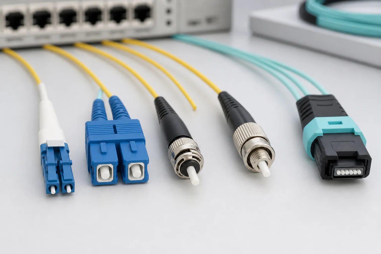
SC (Subscriber Connector)
The SC connector uses a 2.5 mm cylindrical ferrule and a push-pull latching mechanism. Its square profile and snap-in design make it easy to insert and remove without rotation, which reduces stress on the fiber. SC connectors are widely deployed in data centers, telecom central offices, and enterprise networks, particularly for single-mode applications. They offer excellent repeatability and are specified in numerous international standards, including IEC 61754-4.
LC (Lucent Connector)
The LC connector employs a 1.25 mm ferrule—half the diameter of SC—and a latch-based push-pull design. This smaller footprint enables duplex configurations in a single adapter, doubling port density compared to SC. LC has become the de facto standard for high-density patching in data centers and for transceivers such as SFP and QSFP. Its compact size also reduces the force required for mating, which can improve mechanical stability in high-vibration environments.
MPO/MTP (Multi-fiber Push-On)
MPO connectors (and the MTP branded version) house multiple fibers in a single rectangular ferrule, typically 8, 12, or 24 fibers. They use a push-pull mechanism with guide pins to ensure alignment. MPO is essential for parallel optics and high-density backbone cabling, enabling 40G, 100G, and beyond by aggregating multiple lanes. However, MPO termination requires specialized tooling and polishing, and field repair is rarely practical—pre-terminated assemblies are the norm.
ST (Straight Tip) and FC (Ferrule Connector)
ST connectors feature a bayonet-style twist-lock coupling with a 2.5 mm ferrule. They were once common in multimode premises cabling but have largely been superseded by SC and LC. FC connectors use a threaded screw-on coupling, providing robust vibration resistance; they remain popular in test equipment and some industrial settings, though their installation is slower due to threading.
Other Notable Types
Less common but still relevant types include the E2000, which has a protective shutter and a 2.5 mm ferrule, and the CS or SN connectors, which are ultra-compact duplex designs targeting next-generation high-density transceivers. These niche types address specific space or safety requirements but are not yet universal.
Comparison of Key Fiber Optic Connector Types
The table below summarizes typical characteristics of the major connector types. Values are indicative of good-quality components; actual performance depends on manufacturer, polish grade, and fiber mode. Always verify against vendor datasheets and applicable standards.
| Connector | Ferrule Size | Coupling | Typical Insertion Loss (dB) | Typical Return Loss (dB) | Relative Density | Common Use |
|---|---|---|---|---|---|---|
| SC | 2.5 mm | Push-pull | 0.2–0.5 | ≥50 (APC) | Low | Telecom, CATV, enterprise |
| LC | 1.25 mm | Latch | 0.1–0.3 | ≥50 (APC) | High | Data centers, transceivers |
| MPO/MTP | Rectangular (multi-fiber) | Push-pull | 0.3–0.6 (per mated pair) | ≥20 (PC) | Very high | Parallel optics, high-density trunk |
| ST | 2.5 mm | Bayonet | 0.2–0.5 | ≥40 (PC) | Low | Legacy multimode |
| FC | 2.5 mm | Screw | 0.2–0.5 | ≥50 (APC) | Low | Test equipment, industrial |
Note: Insertion loss values are typical for factory-polished connectors; field-terminated connectors may show higher loss. Return loss depends heavily on polish type (PC, UPC, APC) and is not a single number for all variants.
How to Select the Right Connector Type
Choosing among fiber optic connector types requires balancing performance, density, and lifecycle costs. Start by defining the application environment and the fiber mode, then consider density and compatibility.
Application and Environment
For indoor data center patching, LC is often preferred due to its density and compatibility with active equipment. For outdoor or industrial settings where vibration is a concern, FC’s threaded coupling may be more secure, though SC’s push-pull is also robust. If the installation is in a confined space, ultra-compact connectors like CS or SN might be justified, but they require matching transceivers and adapters.
Fiber Mode and Cable Type
Single-mode fibers typically use SC or LC with APC polish for high return loss, especially in RFoG or DWDM systems. Multimode fibers (OM3/OM4) are almost exclusively terminated with LC or MPO for high-speed Ethernet. The cable type—indoor, outdoor, or hybrid—also influences connector choice; for example, armored cables may require ruggedized connectors.
Density and Space Constraints
If rack space is at a premium, MPO allows 12 or 24 fibers in a single connector, dramatically increasing density. LC duplex is the next best for duplex channels. However, higher density often complicates cable management and increases the risk of macrobends. Always plan for bend radius and access.
Compatibility and Standardization
Ensure the chosen connector complies with relevant standards (e.g., IEC 61754 series, TIA-604) to guarantee interoperability. For example, a standard SC connector from one vendor should mate with another vendor’s SC adapter, but MPO polarity and pinning must be carefully matched. Proprietary variants may void warranties or complicate future upgrades.
Performance Limits and Design Tradeoffs
Every connector type has inherent performance limits that engineers must respect. These limits are not arbitrary; they stem from physical constraints of ferrule alignment, polish quality, and material properties.
Insertion Loss and Return Loss
Insertion loss is primarily determined by lateral offset, angular misalignment, and end-face gap. Smaller ferrules (LC) generally achieve lower loss because the fiber is closer to the ferrule center, reducing eccentricity. However, the polish grade (PC, UPC, APC) has a greater effect on return loss: APC (angled) provides the highest return loss by design, but it requires a green-colored connector body to prevent mismating with PC/UPC. Standards such as IEC 61753-1 define performance grades, but typical values are not normative—always refer to the specific standard for pass/fail criteria.
Mechanical Durability
Connector durability is measured in mating cycles. Most connectors are rated for 500 to 1000 cycles, but repeated insertion can degrade performance due to ferrule wear or contamination. The push-pull design of SC and LC reduces torque, which helps maintain alignment, while ST’s bayonet can cause slight rotation. For high-cycle applications, consider connectors with zirconia ceramic ferrules, which resist wear better than stainless steel.
Environmental Limits
Temperature and humidity affect connector performance. Most connectors operate from -40°C to +75°C, but extreme environments may require special materials. Dust and moisture are the biggest enemies; even a microscopic particle can cause high loss or back reflection. Therefore, protective caps and cleaning procedures are critical. In outdoor installations, sealed enclosures are often necessary, and connectors with shutters (e.g., E2000) offer added protection.
Cost and Lifecycle Tradeoffs
Field-terminated connectors (e.g., mechanical splices) are cheaper upfront but may have higher loss and require skilled labor. Factory-terminated connectors (e.g., pigtails) offer better performance but require splicing. MPO assemblies are expensive due to precision multi-fiber ferrules, but they reduce installation time in high-density environments. Over a 10-year lifecycle, the total cost includes not only purchase price but also cleaning supplies, test equipment, and potential re-termination. For example, a low-cost connector that fails early may cost more in downtime than a premium connector that lasts.
In summary, the best fiber optic connector type is the one that meets your performance requirements, fits your density and environmental constraints, and aligns with your budget and maintenance capabilities. Always validate with real-world testing and consult the latest standards to ensure long-term reliability.
Planning Calculations: From Port Count to Spare Capacity
Before any connector is terminated, the network designer must translate physical-layer requirements into a concrete connector budget. This process starts with the link loss budget, which is the sum of all insertion losses along the path, including connectors, splices, and the attenuation of the fiber itself. The budget must remain below the maximum allowable loss for the transceiver type and data rate, as defined by the relevant standard (e.g., IEEE 802.3 for Ethernet).
For multi-fiber systems, the calculation becomes more complex. With MPO/MTP connectors, each array of 12 or 24 fibers introduces its own loss, and the polarity scheme (A-B, A-A, or custom) must be planned to ensure correct end-to-end fiber mapping. A common mistake is to assume that all fibers in an MPO trunk will have identical loss; in practice, ferrule geometry and polishing variations cause per-fiber differences. Therefore, the loss budget should include a worst-case value for each connector, not an average.
Calculating Connector Count and Spare Ports
Determine the number of connectors needed by counting every patch panel, equipment port, and splice point in the path. For a typical data center link from a server to a top-of-rack switch, you might have: server NIC (LC duplex) to patch panel, patch panel to trunk cable (MPO), trunk to distribution panel, and distribution panel to switch (LC). Each mated pair counts as one connector loss. Add a 10–20% spare for future expansion and maintenance—this is a common engineering practice, not a standard requirement.
When planning high-density areas, consider the physical space for connector access. A 1U patch panel with 48 LC duplex ports may require careful cable management to avoid exceeding bend radius. Calculate the number of fibers per rack unit and the required cable tray depth. If using MPO-to-LC fanout cassettes, remember that each cassette occupies a port and adds a connection point, increasing loss and complexity.
Installation Implications: Field Termination vs. Pre-Terminated
The choice between field-terminated and pre-terminated connectors has a major impact on installation time, skill level, and quality. Field termination—using epoxy and polish or mechanical splices—allows custom lengths and routing but requires trained technicians and careful quality control. Pre-terminated assemblies, such as MPO trunks or LC patch cords, are factory-polished and tested, offering consistent performance but requiring accurate length measurement and conduit space for the connectors.
For indoor environments, pre-terminated cabling is often preferred because it reduces installation time and eliminates on-site polishing. However, in tight spaces or when pulling through conduits, the connector size may be a limiting factor. Pulling an MPO connector through a 1-inch conduit is possible, but the bend radius and tensile strength must be respected. Always follow the manufacturer’s installation guidelines for maximum pull force and bend radius.
Polarity and Keying Pitfalls
MPO/MTP connectors have a key that defines orientation. Incorrect keying or polarity can cause complete link failure. For example, a standard A-B polarity uses a key-up connector on one end and key-down on the other, with a crossover in the middle. If the wrong polarity method is used, fibers may not align. Always label both ends and use a polarity tester before deployment.
Another common issue is mismatched ferrule endfaces. A PC (Physical Contact) connector mated with an APC (Angled Physical Contact) connector will cause high loss and potential damage. Ensure that all connectors in a link have the same polish type. This is especially critical when mixing legacy and new components.
Testing and Quality Assurance: Verifying Performance
After installation, every connector should be inspected and tested to ensure it meets the design loss budget. The primary tools are an optical power meter and light source (OLTS) for insertion loss measurement, and an optical time-domain reflectometer (OTDR) for locating faults and characterizing the link. For multi-fiber systems, a MPO tester can measure all fibers simultaneously.
Visual inspection is the first line of defense. Use a fiber inspection microscope to check for dirt, scratches, or pits on the ferrule endface. Even a small particle can cause high reflection and loss. Clean connectors with appropriate tools—lint-free wipes and isopropyl alcohol—before mating. Never touch the endface with fingers.
Interpreting Test Results
Insertion loss values are typically compared against a maximum allowable threshold, such as 0.75 dB for a single mated pair (a common industry benchmark, but not a universal standard). If a link fails, use an OTDR to isolate the fault. The OTDR trace will show a spike at the faulty connector. Remember that OTDRs measure reflected power, not direct loss, so the loss at a connector is calculated from the difference in backscatter levels.
Return loss (reflectance) is also important, especially for high-speed or analog systems. A high return loss (e.g., >50 dB for APC) indicates low reflection. APC connectors are designed to reduce reflection by angling the fiber endface, but they must be mated with other APC connectors.
Field Examples and Caveats
Consider a typical enterprise network upgrade where existing LC connectors are replaced with MPO-based structured cabling. The planning phase must include a loss budget analysis for the new MPO trunk and fanout cassettes. In one scenario, a technician might find that the total link loss exceeds the transceiver’s maximum by 0.2 dB. The cause is often a dirty or damaged MPO connector. Cleaning the endface and re-testing resolves the issue.
Another example: a long outdoor run using single-mode fiber with SC/APC connectors. The installer must ensure that the connectors are rated for outdoor use, with proper sealing and strain relief. A common mistake is to use indoor connectors outdoors, leading to moisture ingress and increased loss over time.
Caveat: Never mix PC and APC connectors in the same link. The angled endface of APC can cause a small air gap when mated with a PC connector, resulting in high loss and back reflection. Always verify polish type before connection.
Caveat: When testing MPO connectors, use a reference patch cord that matches the connector type and polish. A mismatched reference can give false readings. Also, be aware that MPO connectors have a limited number of mating cycles—typically 500 to 1000—so plan for future moves and changes.
By following these planning, installation, and testing practices, you can ensure that your fiber optic connector types are deployed correctly and perform reliably for years. Remember that the key to a successful network is not just choosing the right connector, but also managing the entire lifecycle from design to maintenance.
Failure Modes and Common Mistakes
Even well-specified fiber optic connector types can fail prematurely when installation or maintenance practices are flawed. Understanding the most frequent failure modes helps you avoid costly rework and downtime.
Contamination: The Leading Cause of Failure
Dust, oils, and debris on the ferrule end face are responsible for the majority of field failures. A single particle can create an air gap that increases insertion loss and back reflection, and can even damage the end face when the connector is mated under pressure.
- Inspect before every connection – Use a handheld microscope or automated inspection probe to check the end face. This is not optional for high-performance networks.
- Clean before every connection – Use dry cleaning tools (e.g., reel-based cleaners, click-clean cassettes) for dust, and wet cleaning (lint-free wipes with isopropyl alcohol) for stubborn oils. Allow the surface to dry before mating.
- Cap connectors when not in use – Dust caps prevent contamination and physical damage. Replace caps that are cracked or missing.
Common mistakes include using compressed air (which can deposit moisture or propellant), touching the ferrule with fingers, and reusing contaminated cleaning swabs.
Physical Damage and Misalignment
Scratches, pits, or chips on the ferrule end face cause scattering and increased loss. These often result from improper cleaning, mating with contaminated connectors, or excessive insertion force. Misalignment can also occur if the connector is not fully seated or if the key is not properly oriented.
Another common mistake is over-tightening connectors with threaded couplings. Follow the manufacturer’s recommended torque; over-tightening can distort the ferrule or damage the alignment sleeve.
Incorrect Polarity and Keying
As covered earlier, polarity errors are a frequent source of failure in duplex and parallel optics. Always verify the polarity scheme (A-to-A, A-to-B, etc.) and use the correct keying for your system. A simple visual check of the connector key can prevent a full link failure.
Exceeding Bend Radius and Tensile Limits
Sharp bends in patch cords or pigtails cause macrobending losses, which can be intermittent and difficult to diagnose. Always respect the manufacturer’s minimum bend radius – typically 10 times the cable diameter for patch cords, but check the spec sheet. Tensile loads during pulling or routing can also stress the fiber and cause microcracks.
Procurement Checklist for Fiber Optic Connectors
When purchasing connectors, use a structured checklist to ensure you get the right product for your application. This reduces the risk of compatibility issues and performance shortfalls.
Define Your Requirements
- Connector type – LC, SC, MPO, etc., based on your equipment and density needs.
- Fiber mode – Single-mode (OS2) or multimode (OM3/OM4/OM5). Ensure the connector matches the fiber type.
- Polish type – UPC or APC. APC is required for some RF video and high-power applications; UPC is common for most data and telecom.
- Performance class – Specify insertion loss and return loss limits. For example, single-mode connectors typically have insertion loss ≤ 0.3 dB and return loss ≥ 50 dB for UPC, but these are typical values, not universal standards.
Check Standards and Certifications
Refer to industry standards such as IEC 61754 (connector interfaces) and TIA-604 (FOCIS documents). These define mechanical and optical requirements. Certifications like Telcordia GR-326 for single-mode connectors are often required for carrier-grade networks. Ensure your supplier can provide test data or certificates of conformance.
Evaluate Physical Design and Materials
- Ferrule material – Zirconia ceramic is standard for most connectors; stainless steel or composite ferrules are used in some high-temperature or low-cost applications.
- Housing and boot – Check for strain relief and durability. For harsh environments, look for reinforced bodies and IP-rated options.
- Color coding – Beige for multimode, blue for single-mode UPC, green for APC. This helps prevent mismatching.
Plan for Spares and Compatibility
Order spare connectors and adapters from the same manufacturer and lot to ensure consistent performance. If you are mixing brands, request samples and test them for intermateability. Document the part numbers and test results in your asset records.
Lifecycle Maintenance and Best Practices
Proper maintenance extends the life of your fiber optic connectors and maintains network performance. Implement a routine that includes inspection, cleaning, and documentation.
Establish an Inspection and Cleaning Schedule
For critical links, inspect and clean connectors before every mating. For less critical connections, schedule periodic inspections – e.g., quarterly or annually – depending on the environment. In dusty or industrial settings, increase frequency.
Use a two-step process: inspect first, then clean if needed. After cleaning, re-inspect to confirm the end face is clean. Never mate a connector that fails inspection.
Handle Connectors with Care
- Always hold the connector body, not the cable or boot.
- Do not pull on the cable to disconnect – use the release mechanism.
- Keep dust caps on when not in use.
- Store connectors in a clean, dry environment, away from chemicals and extreme temperatures.
Document and Track Performance
Maintain a log of insertion loss and return loss measurements for each link. This helps identify gradual degradation and plan for remediation before a failure occurs. Use an OTDR or power meter and light source for periodic testing.
Actionable Recommendations and Conclusion
Selecting the right fiber optic connector types is only the first step. To ensure long-term reliability, follow these actionable recommendations:
- Standardize on a minimal set of connector types – Reduce complexity by using one or two types across your network. For example, LC for patching and MPO for high-density trunking.
- Train your team – Ensure installers and technicians are certified in fiber optic connector handling and cleaning. Regular refresher courses prevent bad habits.
- Invest in quality inspection tools – A good inspection probe and cleaning kit are inexpensive compared to the cost of a network outage.
- Perform end-to-end testing after any change – Always verify insertion loss and return loss after installing or re-terminating connectors.
- Plan for future upgrades – Choose connectors that support higher data rates, such as MPO for 40G/100G/400G, to avoid re-cabling later.
In conclusion, the performance of your fiber optic network depends as much on how you handle and maintain connectors as on the initial selection. By understanding failure modes, following a procurement checklist, and implementing a lifecycle maintenance program, you can maximize uptime and minimize total cost of ownership. Remember to always refer to the latest standards and manufacturer specifications for your specific components.
Frequently Asked Questions
What are the main fiber optic connector types and how do they differ?
Common types include SC, LC, ST, FC, and MTP/MPO. They differ in size, ferrule (2.5mm for SC/ST/FC, 1.25mm for LC, and multi-fiber for MTP/MPO), and coupling mechanism (push-pull, bayonet, screw). SC and LC are prevalent in data centers and telecom; ST and FC are older but still used in industrial settings. MTP/MPO supports high-density parallel optics.
How do I choose the right fiber optic connector for my application?
Consider fiber type (single-mode vs. multimode), connector style (simplex, duplex, or multi-fiber), and environment (indoor, outdoor, high-vibration). For high-density data centers, LC or MTP/MPO are typical. For long-haul telecom, SC or LC with single-mode fiber. Ensure compatibility with existing equipment and standards like TIA-568.
Are LC and SC connectors interchangeable? Can I use an adapter to connect them?
LC and SC are not directly interchangeable due to different ferrule sizes (1.25mm vs 2.5mm). However, hybrid adapter cables or mating adapters (e.g., LC-to-SC) can connect them, but this introduces additional loss and is not recommended for permanent installations. Always use matching connectors for optimal performance.
What is the typical insertion loss for different fiber optic connectors?
Typical insertion loss for polished connectors (PC, UPC) is ≤0.3 dB, and for angle-polished (APC) it's ≤0.3 dB as well, but APC is used for high-power or RFoG. MTP/MPO connectors have higher loss, typically ≤0.5 dB for multimode and ≤0.75 dB for single-mode. Always check manufacturer specs and industry standards like IEC 61753.
What is the difference between UPC and APC polish, and which should I use?
UPC (Ultra Physical Contact) has a slight dome shape with a 0° angle, providing low back reflection (-50 dB). APC (Angled Physical Contact) has an 8° angle, yielding even lower back reflection (-60 dB) and is used in applications sensitive to reflections, like FTTx and RF video. Use APC for single-mode with green connectors; UPC for most others.
How do I properly clean and test fiber optic connectors?
Clean connectors using dry or wet-dry cleaning methods with lint-free wipes and ferrule cleaners. Inspect with a microscope to ensure no contamination. Test insertion loss and return loss using an OLTS or OTDR with appropriate launch cables. Always use reference-grade test jumpers and follow TIA-526 or IEC 61280 standards.
Related In-Depth Guides
Continue with these focused engineering guides:







