
When you are choosing fiber optic connectors, the question UPC vs APC connector comes down to one core difference: the geometry of the ferrule end face and the resulting return loss performance. In short, UPC (Ultra Physical Contact) connectors have a domed, polished end face that provides excellent return loss (typically ≥50 dB), while APC (Angled Physical Contact) connectors have an angled end face (typically 8°) that achieves superior return loss (typically ≥60 dB). For most single-mode applications requiring high reflection suppression—such as GPON, XGS-PON, or RFoG—APC is the preferred choice. However, UPC remains common in patch cords and equipment where the connector standard or existing infrastructure dictates its use.
What Are UPC and APC Connectors?
UPC and APC are two polishing styles for fiber optic connector ferrules—the cylindrical tip that holds the fiber. The polishing process shapes the end face to ensure physical contact between two mated fibers, minimizing air gaps that cause reflections.
UPC (Ultra Physical Contact)
UPC connectors feature a slightly convex (domed) end face. The curvature ensures that the fiber cores are pressed together when mated. The polish is smooth and produces a low insertion loss, but the reflected light returns directly along the fiber axis. This axial reflection is why UPC return loss is good but not exceptional—typically in the range of 50 dB or higher.
APC (Angled Physical Contact)
APC connectors have an end face that is polished at an angle—typically 8 degrees relative to the fiber axis. The angle is standardized in many connector specifications (e.g., IEC 61754 series) for angled ferrules. When two APC connectors are mated, the angled surfaces fit together, and any reflected light is directed into the cladding at the angled interface rather than returning along the core. This design dramatically reduces back reflection, achieving return loss values of 60 dB or more.
Why Return Loss Matters
Return loss (also called reflectance or back reflection) measures how much of the incident light is reflected back toward the source. It is expressed in decibels (dB); a higher value indicates less reflection. In high-speed or analog optical systems, reflections can cause laser instability, signal distortion, and increased bit error rates.
For example, in passive optical networks (PON), the optical line terminal (OLT) uses a laser that is sensitive to reflected light. Even small reflections can interfere with the transmitted signal, especially in video overlay services where analog RF signals are carried. APC connectors are often mandated in such systems to keep reflections below a threshold that would degrade performance.
Core Technical Differences Between UPC and APC
The primary differences are the end-face geometry, return loss performance, and color coding—but there are also practical implications for compatibility and testing.
- End-face angle: UPC is flat (0°), APC is angled (typically 8°).
- Return loss: UPC ≥50 dB typical, APC ≥60 dB typical. (These are typical values, not universal limits; actual performance depends on polish quality and mating.)
- Insertion loss: Both can achieve low insertion loss (typically <0.3 dB for single-mode), but APC may have slightly higher loss due to the angle.
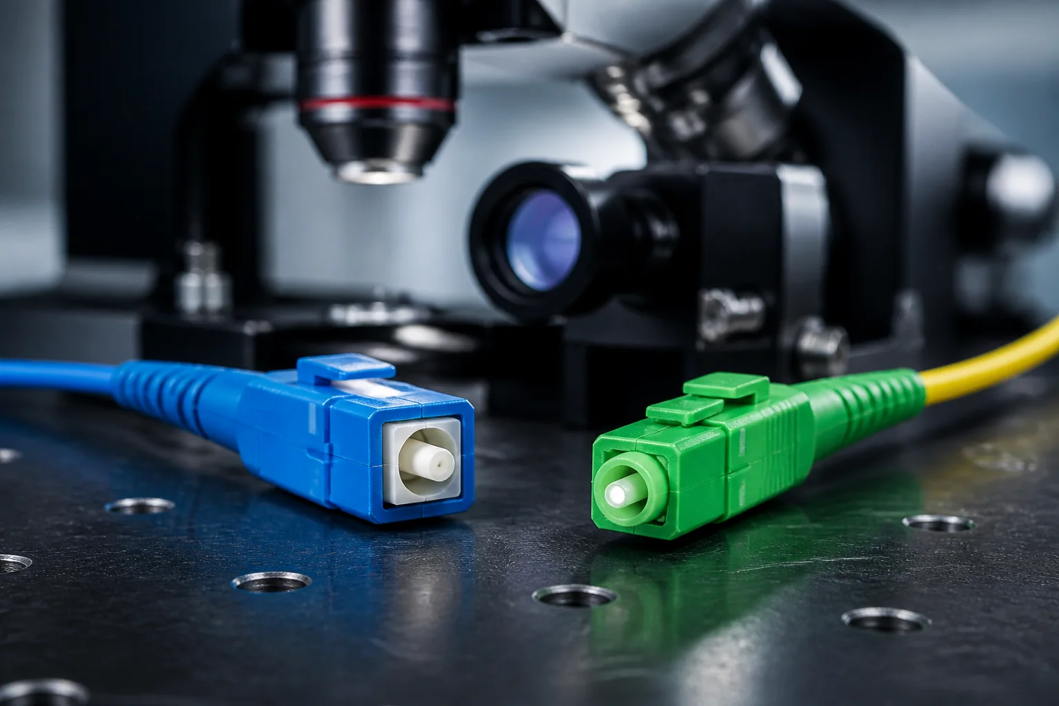
- Color coding: UPC connectors are usually blue, APC connectors are green. This helps prevent mismatching.
- Compatibility: UPC and APC connectors are not compatible—mating them can damage the ferrules and cause high reflection.
When the Question Matters
The UPC vs APC decision is critical in several scenarios:
- New installations: Choosing the right polish from the start avoids costly rework.
- Upgrading to higher-speed PON: Modern PON standards (e.g., 10G-EPON, XGS-PON) often specify APC for the optical distribution network (ODN) to maintain signal integrity.
- Testing and measurement: When using an optical time-domain reflectometer (OTDR), the launch cable must match the connector type of the network under test to avoid misleading reflections.
- Mixing with existing infrastructure: If your existing patch panels or equipment use UPC, you may need to stay with UPC or use hybrid patch cords with different polish on each end.
Standardization and Typical Values
Return loss requirements are often specified in industry standards. For example, IEC 61753-1 defines performance categories for connectors, and some applications (like high-bit-rate transmission) may require return loss >45 dB, which both UPC and APC can meet. However, for analog video or high-power laser systems, APC is often preferred because its return loss is consistently higher.
It is important to note that the numbers I mentioned (50 dB, 60 dB) are typical values observed in quality connectors, not absolute guarantees. Always consult the manufacturer’s datasheet for specific performance. Also, the 8° angle is a common industry practice, but some specialized connectors may use different angles—always verify the specification.
In summary, the choice between UPC and APC hinges on the required return loss, the application, and the existing infrastructure. For most modern single-mode networks, especially those carrying sensitive signals, APC is the safer choice. But UPC remains relevant in many legacy systems and in short-distance patch cords where reflections are less critical.
UPC vs APC Connector: Side-by-Side Comparison
When you need to choose between UPC and APC, the decision often comes down to a few measurable parameters. The table below summarizes typical values for single-mode connectors, but note that exact numbers depend on the connector grade and the test method. Standards such as IEC 61753-1 define minimum requirements for return loss, but manufacturers often exceed them.
| Parameter | UPC | APC |
|---|---|---|
| Ferrule end-face geometry | Flat or slightly convex, perpendicular to fiber axis | Angled at 8° (typical) relative to fiber axis |
| Typical return loss (single-mode) | ≥50 dB (typical high-grade) | ≥60 dB (typical high-grade) |
| Insertion loss (typical) | ≤0.2 dB (mated pair) | ≤0.3 dB (mated pair) |
| Reflected power at 1 mW input (example) | ~0.00001 mW (if 50 dB) | ~0.000001 mW (if 60 dB) |
| Color coding | Blue (common) | Green (common) |
| End-face polish type | Ultrasonic polish, no angle | Angled polish, typically 8° |
| Common applications | Data centers, enterprise networks, patch cords | FTTH, PON, RFoG, high-power laser systems |
The most critical difference is the angled end-face. In an APC connector, the angle forces reflected light to leak out of the fiber core instead of traveling back toward the source. That is why APC achieves higher return loss. However, the angle also means that APC connectors will not mate with UPC connectors without causing damage and poor performance.
Decision Criteria: How to Choose Between UPC and APC
Choosing between UPC and APC is not about which is “better” in absolute terms—it is about matching the connector to the system requirements. Use these criteria to guide your selection.
1. System Return Loss Requirement
Check the optical budget and reflection sensitivity of your system. If the equipment specification calls for return loss greater than 50 dB, APC is usually required. For example, analog RF video transmission and some high-speed coherent systems are sensitive to reflections. In contrast, many digital data center links work fine with UPC’s typical 50 dB return loss.
2. Existing Infrastructure and Compatibility
Never mix UPC and APC in the same link. If your patch panel, pigtails, or transceivers are already terminated with APC, you must use APC throughout. Similarly, if you are extending an existing UPC-based network, stick with UPC to avoid the risk of physical damage. The end-face geometry is incompatible—mating them can crack the ferrule or cause high insertion loss.
3. Application Type
Passive optical networks (PON) and RF over glass (RFoG) almost universally use APC because reflections can degrade the video signal. For standard Ethernet or Fibre Channel in data centers, UPC is common because the link budgets are more forgiving. However, always verify with your equipment vendor.
4. Future-Proofing and Standards
Some standards, such as those for 400G Ethernet, may recommend APC for certain optical modules, but this is not universal. Check the relevant IEEE or ITU specifications for your application. When in doubt, consult your system architect or the transceiver manufacturer.
Worked Example: Selecting a Connector for a PON Deployment
Imagine you are designing an FTTH network using GPON technology. The optical line terminal (OLT) and optical network unit (ONU) are specified with APC connectors. The splitter modules also have APC ports. Your task is to choose the patch cords that connect the OLT to the splitter and the splitter to the ONU.
First, note that GPON uses wavelengths around 1490 nm (downstream) and 1310 nm (upstream). Reflections from connectors can interfere with the laser stability at the OLT. The GPON standard (ITU-T G.984) does not mandate a specific connector type, but the industry practice is to use APC to achieve return loss above 60 dB, which minimizes reflection-induced noise.
Second, check the physical compatibility. Since all active and passive components have APC interfaces, you must use APC patch cords. If you mistakenly order UPC cords, they will not mate correctly with the APC adapters—the angled end faces will not align, leading to air gaps and high loss. The connectors might even be damaged if forced.
Third, verify the return loss of the chosen patch cords. A typical high-quality APC patch cord will have a return loss of ≥60 dB, which is more than sufficient for GPON. Insertion loss should be ≤0.3 dB per mated pair. These are typical values; the actual performance should be confirmed with an optical time-domain reflectometer (OTDR) after installation.
Finally, consider the color coding: APC connectors are green, while UPC are blue. This visual cue helps prevent accidental mixing. In your deployment, ensure that all patch cords, adapters, and pigtails are green to avoid confusion.
Selection Guidance: A Simple Checklist
To make the final decision, follow this checklist:
- Identify the application: Is it a PON, RFoG, or high-speed digital link? If it involves analog video or high-power lasers, lean toward APC.
- Check existing hardware: Look at the connectors on your transceivers, patch panels, and test equipment. Match the connector type exactly.
- Review system specifications: Look for return loss requirements in the equipment data sheets. If they specify >50 dB, choose APC.
- Consider the environment: In dirty or dusty environments, APC’s angled end face can be more forgiving to small particles, but both types need proper cleaning.
- Plan for maintenance: Ensure your technicians have the correct inspection probes and cleaning tools for the chosen connector type. APC requires specialized scopes and cleaners.
In summary, the UPC vs APC connector decision is driven by performance needs, compatibility, and application. Always prioritize matching the existing system over achieving the highest possible return loss. When in doubt, consult the equipment manufacturer or a fiber optic specialist.
Installation and Testing Implications
Choosing between UPC and APC connectors is not just a design decision; it also affects how you terminate, inspect, and test your fiber links. The physical differences—especially the 8° angle on APC—demand different handling and verification procedures.
Termination and Polishing
Field termination of APC connectors requires more care than UPC. The angled ferrule end face must be polished with a fixture that holds the angle precisely. If you use a standard UPC polishing puck, you will produce an incorrect geometry, leading to poor return loss and potential air gaps. For factory-terminated pigtails and patch cords, the process is automated, but for field-installable connectors, always use the manufacturer’s specified tooling.
Inspection and Cleaning
Both UPC and APC end faces must be inspected with a scope that can handle the angle. Many modern inspection probes automatically adjust for APC, but older scopes may not. If you inspect an APC connector with a probe set for UPC, the image will be out of focus, and you might miss contamination or damage. Cleaning is similar for both, but remember that APC’s angled surface can collect debris in the fiber core area more easily; use dry cleaning or solvent as recommended by the connector manufacturer.
Testing Return Loss and Insertion Loss
Return loss testing requires an OLTS (Optical Loss Test Set) with a return loss module or an OTDR. For accurate return loss measurements, the test reference cords must match the connector type under test. If you are testing an APC link, use APC test cords; using UPC test cords will yield misleading results. Insertion loss testing is less sensitive to connector type, but the launch and receive cords must still match the system connectors to avoid geometry mismatch.
Common Mistakes to Avoid
- Mixing UPC and APC in the same link: This is the most frequent error. A UPC connector plugged into an APC adapter (or vice versa) can damage the ferrule and cause high insertion loss. Always verify connector type before mating.
- Using the wrong adapter: UPC and APC adapters are not interchangeable. APC adapters are often green, but color is not a reliable indicator—always check the geometry.
- Assuming all green connectors are APC: While many manufacturers use green for APC, some use blue for UPC and green for APC, but there is no universal standard. Always confirm with the datasheet.
- Neglecting to clean before testing: Contamination is a leading cause of test failures. Clean both ferrule end faces before every connection.
- Forgetting to update test equipment settings: Some OLTS units require you to select the connector type for return loss calculations. If set incorrectly, your measurements will be off.
Buyer Checklist for UPC vs APC Connectors
When purchasing connectors, patch cords, or pre-terminated assemblies, keep this checklist handy:
- Confirm the connector type (UPC or APC) for every component in the link.
- Match the connector type on both ends of a patch cord—do not mix.
- Verify that adapters and couplers match the connector type.
- Check the polishing style on the datasheet or packaging; do not rely on color alone.
- For high-return-loss applications (e.g., analog RFoG, certain DWDM), choose APC.
- For standard digital transmission (e.g., Ethernet, most PON), UPC is often sufficient, but verify system requirements.
- If you are extending an existing network, match the installed connector type to avoid adapters or re-termination.
- Order test cords that match the connector type of your network.
- Consider the availability of field termination kits—APC may require specialized tools.
Practical Recommendation and Conclusion
In most enterprise and data center environments, UPC connectors are the default choice because they are cost-effective and provide adequate return loss for digital signals. However, for analog video, high-density DWDM, and any system where reflections can degrade performance, APC is the safer choice. The key is to standardize on one type per network segment to avoid accidental mismatches.
If you are starting a new installation and have no legacy constraints, evaluate your system’s return loss requirement. If it is not explicitly specified, UPC will likely meet your needs. But if you are deploying PON with RF video overlay, APC is often recommended by industry best practice, though not always a hard requirement—check your equipment specifications.
Finally, always document your connector types clearly and train your installation team on the differences. A small mistake in connector selection can lead to costly rework and signal degradation. By following the checklist and understanding the testing implications, you can ensure a reliable fiber network.
Frequently Asked Questions
What is the main difference between UPC and APC fiber connectors?
UPC (Ultra Physical Contact) connectors have a flat ferrule end-face with a slight dome, while APC (Angled Physical Contact) connectors feature an 8-degree angled ferrule end-face. The angle reduces back reflection, giving APC a higher return loss.
Why are APC connectors green and UPC connectors blue?
Color coding is a standard industry practice to visually distinguish connector types. UPC connectors are typically blue, and APC connectors are green, helping technicians avoid mismatching them in the field.
Can I connect a UPC connector to an APC connector?
No, UPC and APC connectors are not compatible. The angled end-face of APC and the flat end-face of UPC do not align properly, causing high insertion loss and poor return loss. Always match connector types.
What is return loss and why does it matter?
Return loss measures the amount of light reflected back toward the source, expressed in decibels (dB). Higher return loss (e.g., 50 dB for APC) means less reflection, which is critical for analog RF and high-speed digital signals to prevent interference and signal degradation.
Which connector type should I choose for single-mode vs multimode fiber?
Both UPC and APC are available for single-mode and multimode fibers. However, APC is commonly used in single-mode applications like FTTH and CATV, while UPC is often used in multimode data centers. The choice depends on your network's return loss requirements and existing infrastructure.
Are APC connectors required for all fiber optic networks?
No, APC is not required for all networks. Many digital systems, such as standard Ethernet, can work well with UPC connectors. APC is particularly beneficial for analog video and RF-over-fiber, or when return loss is critical. Always check your equipment specifications.
What are typical return loss values for UPC and APC connectors?
Typical return loss for UPC connectors is around 50 dB, while APC connectors achieve 60 dB or higher. These values exceed the minimum requirements of most standards, but actual performance depends on connector quality and polishing.
Complete topic guide: Fiber Optic Connector Types: Complete Guide.







