
Choosing the right fiber optic patch cord is not a trivial accessory decision—it directly affects link loss, reliability, and long-term maintenance costs. This fiber optic patch cord guide explains the essential types, terminology, and engineering trade-offs so you can specify the correct cable for your network architecture, whether you are deploying data center interconnects, enterprise LANs, or telecom outside plant.
Essential Definitions and System Role
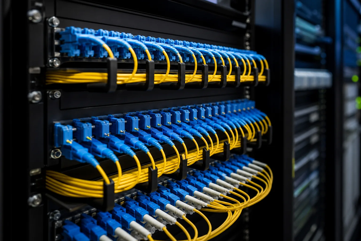
A fiber optic patch cord (also called a jumper or patch cable) is a length of optical fiber terminated with connectors on both ends. It connects equipment ports, patch panels, or optical devices, forming the flexible link between permanent cabling and active components. Unlike bulk fiber, patch cords are designed for frequent handling and reconfiguration.
What Makes a Patch Cord Different from Pigtails or Trunk Cables
- Patch cord: Connectors on both ends, ready to plug in.
- Pigtail: Connector on one end, bare fiber on the other, meant for splicing to a distribution cable.
- Trunk cable: Multiple fibers in a single jacket, often with MPO connectors, used for high-density backbone runs.
In a typical structured cabling system, patch cords are used in the equipment room and at the work area. They provide the final connection between the switch port and the patch panel, or between the wall outlet and the end device. Their performance directly contributes to the total channel loss budget.
Core Parameters That Define Performance
Every patch cord specification revolves around a few critical parameters. Understanding these helps you compare products and avoid mismatches.
Fiber Type: Singlemode vs. Multimode
The fiber core diameter determines the light propagation mode. Singlemode fiber (SMF) has a small core (typically 9 µm) and supports only one mode, enabling long-distance, high-bandwidth transmission. Multimode fiber (MMF) has a larger core (50 µm or 62.5 µm) and supports multiple modes, suited for short-reach applications like data centers.
Choosing the wrong fiber type is a common error. Singlemode patch cords can be used with multimode transceivers only with mode-conditioning cords—a specific type of patch cord that launches light off-center. Conversely, using multimode patch cords on singlemode systems will cause excessive loss and is not recommended.
Connector Types and Polish
Connectors must match the equipment ports and the cabling infrastructure. Common types include LC, SC, ST, and MPO. The ferrule polish—PC, UPC, or APC—affects return loss. APC (angled) connectors are typically used for singlemode applications requiring low reflectance, such as RF video or passive optical networks. UPC is standard for most data and telecom links.
Mixing polish types (e.g., UPC with APC) can damage connectors and cause high loss. Always verify connector compatibility before ordering.
Insertion Loss and Return Loss
Insertion loss (IL) is the optical power lost when light passes through the connector. Return loss (RL) measures how much light is reflected back toward the source. Lower IL and higher RL are generally better. Standards such as IEC 61753 define performance grades, but typical values for premium patch cords are IL below 0.3 dB and RL above 50 dB for UPC.
Note: These are typical engineering values, not universal requirements. Always consult the applicable standard for your application.
Engineering Decisions You Must Make
Selecting a patch cord involves more than picking a length. You must evaluate several trade-offs.
Length and Routing
Measure the physical path, including service loops and slack. Too short a cord causes strain on connectors; too long adds unnecessary loss and clutter. Use structured cabling standards (e.g., TIA-568) for maximum channel lengths, but for patch cords, practical lengths range from 0.5 m to 50 m.
Jacket Material and Fire Rating
The outer jacket must meet local fire codes. Plenum-rated (e.g., OFNP) jackets are required in air-handling spaces; riser-rated (OFNR) for vertical shafts; and LSZH (low smoke zero halogen) for areas with human occupancy. Choose based on your building’s safety regulations.
Polarity and Orientation
For duplex patch cords (two fibers), polarity ensures that transmit and receive signals align correctly. Standards define methods A, B, and C for MPO-based systems. For LC/SC duplex cords, the key orientation (A-to-B or A-to-A) must match the equipment. Incorrect polarity is a leading cause of link failure.
Bend Sensitivity and Durability
Bend-insensitive fibers (e.g., G.657.A1) allow tighter bends without significant loss, useful in crowded racks. However, they are not a substitute for proper cable management. For high-flex applications, use reinforced or armored patch cords, but note that they are less flexible and heavier.
Selection Checklist: From Requirements to Specification
To make a sound decision, follow this systematic approach:
- Determine the optical transceiver type and fiber mode (SMF or MMF).
- Identify the connector types on both ends—they may differ (e.g., LC to SC).
- Check the polish type (UPC or APC) and ensure consistency.
- Measure the required length, adding 10-15% for slack.
- Select the jacket rating based on installation environment.
- Define polarity for duplex or MPO cords.
- Specify performance grades for IL and RL, referencing relevant standards.
- Consider environmental factors: temperature, moisture, chemical exposure.
By working through this checklist, you will avoid common pitfalls and ensure that your fiber optic patch cords perform reliably for years. The remainder of this guide will dive deeper into each connector type, fiber class, and application-specific recommendations.
Major Architectures and How Patch Cords Fit In
In modern fiber networks, patch cords are not one-size-fits-all. Their role depends on the architecture they serve. Understanding the major types helps you choose the right cord for your application.
Point-to-Point Links
In simple point-to-point links—common in data center interconnects or direct server-to-switch connections—patch cords connect transceivers to patch panels or directly between devices. Here, the key is to match the transceiver interface (e.g., LC duplex) and ensure the fiber type and connector polish align with the system’s optical budget.
Structured Cabling and Cross-Connects
In structured cabling, patch cords are used at both ends of a permanent link: from the switch to the patch panel, and from the outlet to the end device. This architecture requires careful attention to polarity, especially with duplex or MPO-based systems. The total channel loss includes the permanent link plus both patch cords, so low insertion loss is critical.
Parallel Optics and MPO-Based Systems
High-speed networks (e.g., 40G, 100G, 400G) often use parallel optics with MPO connectors. Patch cords in these systems may be MPO-to-MPO trunk cables or fan-out cords (MPO to multiple LC duplex). Polarity methods (A, B, C) and key-up/key-down orientation are essential to ensure correct fiber mapping.
Centralized vs. Distributed Cabling
In centralized cabling, long backbone cables run from a central location to consolidation points, with patch cords at both ends. In distributed cabling, shorter runs and zone cabling are used, which may reduce the number of patch cords but increase the need for flexible, bend-insensitive designs.
Comparison of Common Patch Cord Types
The table below compares typical patch cord types based on fiber, connector, and application. Values are typical engineering targets, not normative limits.
| Type | Fiber Core | Connector Options | Typical Application | Insertion Loss (typical) | Bend Sensitivity |
|---|---|---|---|---|---|
| Single-mode OS2 | 9/125 µm | LC, SC, FC, ST | Long-haul, WAN, data center backbone | ≤ 0.3 dB (per mated pair) | Low (standard) / High (bend-insensitive) |
| Multimode OM3 | 50/125 µm | LC, SC, MPO | Data center, LAN, 10G/40G/100G | ≤ 0.3 dB (per mated pair) | Moderate |
| Multimode OM4 | 50/125 µm | LC, SC, MPO | High-speed data center, 100G/400G | ≤ 0.3 dB (per mated pair) | Moderate |
| Multimode OM5 | 50/125 µm | LC, SC, MPO | SWDM, short wavelength division multiplexing | ≤ 0.3 dB (per mated pair) | Moderate |
| Armored | Any | Any | Industrial, harsh environments | Same as underlying fiber | High (due to armor) |
| Bend-insensitive | Any | Any | Tight bends, cable management | Same as underlying fiber | Very low (improved) |
Note: Insertion loss values are typical for factory-terminated cords; field-terminated cords may have higher loss. Always refer to the relevant standard (e.g., IEC 61753-1) for grade-specific limits.
Selection Criteria: Matching the Cord to the System
Choosing the right patch cord involves more than just fiber type and connector. Use the following criteria to narrow down your options.
Optical Performance Requirements
- Insertion loss: Lower is better, especially in long links or with many mated pairs. Typical factory cords achieve ≤0.3 dB, but some applications require ≤0.15 dB.
- Return loss: High return loss (e.g., >50 dB for singlemode) reduces reflections. This is critical for analog or high-power systems.
- Bandwidth: For multimode, ensure the fiber grade (OM3/OM4/OM5) supports your data rate and distance.
Environmental and Mechanical Factors
- Bend radius: If your routing has tight bends, choose bend-insensitive fiber (e.g., G.657.A1/A2 for singlemode).
- Jacket material: PVC, LSZH, or plenum-rated jackets depend on fire codes and installation environment. Plenum-rated (e.g., OFNP) is required in air-handling spaces per NEC.
- Durability: Armored cords or ruggedized boots protect against crushing and pulling.
Connector and Polarity Considerations
- Connector type: Match the equipment interfaces. LC is dominant in data centers; SC is common in enterprise; MPO is for high-density parallel optics.
- Polish type: UPC for singlemode (low insertion loss), APC for singlemode where return loss is critical (e.g., RFoG). Multimode typically uses PC or UPC.
- Polarity: For duplex or MPO systems, ensure correct polarity (A/B/C methods) to maintain transmit-receive alignment.
Standards and Compliance
Patch cords should meet industry standards such as IEC 61754 for connectors, IEC 60793 for fiber, and TIA-568 for cabling. Fire safety ratings follow local codes (e.g., NEC in the US). Always verify that the cord’s performance meets the requirements of your specific application, not just the minimum standard.
Performance Limits and Design Tradeoffs
Every design choice involves tradeoffs. Understanding these limits helps you avoid over- or under-specifying.
Insertion Loss vs. Durability
Lower insertion loss often requires precise polishing and high-quality ferrule materials, which can increase cost. Conversely, ruggedized cords with extra armor may have slightly higher loss due to additional stress on the fiber. Balance optical performance with mechanical robustness.
Bend Insensitivity vs. Cost
Bend-insensitive fibers (e.g., G.657.A2) allow tighter bends but may cost more than standard G.652.D. In data centers where space is tight, the extra cost is often justified. For long outdoor runs, standard fiber may be sufficient.
Connector Density vs. Ease of Use
MPO connectors offer high density but require careful polarity management and are less forgiving to field termination. LC duplex connectors are easier to handle but take more space. Choose based on your installation and maintenance capabilities.
Length and Signal Attenuation
Longer patch cords introduce more attenuation, but for typical lengths (1–10 m) the difference is negligible. However, in high-loss budgets, every tenth of a dB counts. Keep patch cords as short as possible without straining the cable management.
Normative vs. Typical Values
Standards like IEC 61753-1 define performance grades (e.g., Grade B for insertion loss ≤0.25 dB). These are normative limits. Typical values from manufacturers are often better, but you should design to the standard to ensure interoperability. Always consult the latest standard for your region and application.
Planning Calculations: From Link Budgets to Patch Cord Lengths
Before you order a single patch cord, you need to know how much optical loss your link can tolerate and how much physical length you actually need. This is where the fiber optic patch cord guide becomes a practical tool, not just a catalog reference.
Calculating Link Loss Budgets
A link loss budget sums the expected losses of every component between transmitter and receiver. Patch cords contribute through connector loss and, for long runs, fiber attenuation. The budget must stay below the system’s maximum allowable loss, which is defined by the transceiver standard (e.g., IEEE 802.3 for Ethernet). That maximum is a normative requirement; your calculated budget is a design estimate.
Typical engineering practice assigns 0.3–0.5 dB per mated connector pair, but these are typical values, not guaranteed limits. Always use the actual insertion loss data from your chosen patch cord manufacturer. For multimode links, also account for modal dispersion, though patch cords are usually too short to matter.
Field example: A 100-meter single-mode link with two patch cords (four connectors) and two fusion splices. If the transceiver allows 3.5 dB total loss, and you estimate 0.4 dB per connector, 0.1 dB per splice, and 0.2 dB for fiber attenuation, your budget is 4×0.4 + 2×0.1 + 0.2 = 2.0 dB. That leaves 1.5 dB of margin. If you later add a patch panel, you’ll need to recalculate.
Estimating Patch Cord Lengths
Measure the physical path from device to device, including vertical risers, horizontal trays, and service loops. Add 10–15% extra for routing slack and future moves. For rack environments, use the actual cable manager width and depth—don’t guess. A common mistake is ordering 1-meter cords when 0.5 meters would suffice, creating loops that obstruct airflow.
For high-density patching, consider using length-labeled cords to simplify inventory and troubleshooting. Some operators standardize on a few lengths (0.5, 1, 2, 3 meters) to reduce stock complexity.
Installation Implications: Physical Handling and Routing
Patch cords are the most handled component in a network. Their installation directly affects long-term reliability.
Bend Radius and Pulling Tension
Never exceed the manufacturer’s minimum bend radius, even during installation. For standard cords, the typical dynamic bend radius is 20 times the cable diameter; static is 10 times. Bend-insensitive fibers allow tighter bends, but the connector strain relief still has limits. Use a cable puller with a tension gauge if you must pull cords through conduit, though patch cords are usually hand-routed.
Field caveat: A technician once routed a patch cord through a sharp 90-degree conduit bend and immediately saw high loss. The fiber had microcracks from excessive tension. Always leave slack at both ends and avoid tight zip ties.
Connector Protection and Cleaning
Dust caps stay on until the moment of connection. Before mating, inspect the ferrule with a scope and clean if needed. Use only dry cleaning or approved solvent—never saliva or water. Contaminated connectors are the leading cause of intermittent failures.
In high-vibration environments (e.g., factory floors), use locking connectors or strain-relief boots. For patch panels, ensure the cord’s bend radius is not violated when routing to adjacent ports.
Testing and Quality Assurance: Verifying Performance
Testing is not optional. It validates that your patch cords meet specifications and that your installation didn’t introduce faults.
Insertion Loss and Return Loss Testing
Use an optical loss test set (OLTS) to measure end-to-end loss. Compare against your budget. For return loss (reflectance), use an OTDR or a return loss meter. High reflectance can destabilize laser sources, especially in single-mode systems.
Normative standards, such as IEC 61300-3-4, define test methods, but pass/fail criteria are typically set by the system designer. For example, a typical acceptance criterion for a patch cord is ≤0.5 dB insertion loss, but this is not a universal limit—check your project specs.
OTDR Testing and Event Interpretation
An OTDR can locate faults along the fiber, but it has limitations with short patch cords. The dead zone—the distance after a connector where the OTDR cannot see events—can mask issues. Use a launch cable (a known good reference fiber) to move the dead zone away from the connector under test.
Field example: A technician used an OTDR without a launch cable and saw a large loss event at the first connector. After adding a 100-meter launch cable, the event disappeared, proving the connector was fine. The apparent loss was an artifact.
Polarity and Continuity Checks
For duplex cords, verify that the transmit and receive fibers are correct (A-to-B or A-to-A depending on system). Use a visual fault locator (VFL) to trace continuity and polarity. For MPO cords, use a polarity tester or a light source and power meter to confirm the fiber mapping.
Quality assurance also involves documentation. Record test results for each link, including patch cord identifiers, test dates, and measured values. This data is invaluable for future troubleshooting.
Field Caveats and Best Practices
Real-world experience reveals several pitfalls that a fiber optic patch cord guide should highlight.
- Mixing connector types: Never force an SC into an LC. Use hybrid cords or adapters designed for the purpose.
- Over-tightening connectors: Hand-tighten only; wrenches can damage the ferrule.
- Ignoring bend radius at patch panels: Even if the fiber allows tight bends, the cable jacket may kink, causing stress on the connector.
- Using patch cords as permanent links: Patch cords are designed for flexibility, not for permanent routing. For permanent runs, use splice-on pigtails or field-terminated connectors.
Another caveat: In data centers, color coding is often used to distinguish fiber types (e.g., aqua for OM3, yellow for OS2). But this is a convention, not a standard. Always label cords with their actual specifications.
Finally, remember that patch cords are consumable. They wear out with repeated mating. Inspect ferrules regularly and replace cords that show scratches or contamination that cannot be cleaned.
Failure Modes and Common Mistakes
Even a well-specified patch cord can fail prematurely if installation or handling practices are flawed. Understanding the most frequent failure modes helps you avoid costly downtime and rework.
Mechanical Stress and Fiber Breakage
The leading cause of field failures is excessive mechanical stress. Patch cords are not designed to bear tensile loads; they are meant to be routed and left in place. Common mistakes include:
- Using patch cords as pull strings during cable installation.
- Exceeding the recommended minimum bend radius, especially at connector strain-relief boots.
- Pinching cords under equipment racks or furniture.
- Allowing cords to hang unsupported from patch panels, which can stress the connector termination.
Typical bend radius limits for non-bend-insensitive fibers are around 30 mm for patch cords, but always consult the manufacturer’s datasheet. Bend-insensitive fibers allow tighter bends, but they are not immune to damage—micro-bends can still increase attenuation.
Contamination and Connector Damage
Dust and oil are the most common causes of high insertion loss and intermittent failures. A single speck of dust on a fiber endface can cause back-reflection and signal degradation. Common mistakes:
- Not using dust caps during storage and transport.
- Touching the ferrule endface with fingers.
- Reusing contaminated cleaning materials.
- Mating connectors without inspecting and cleaning them first.
Always clean connectors before every mating, even if they appear clean. Use appropriate tools: lint-free wipes and optical-grade cleaning fluid, or dry cleaning cartridges designed for the connector type.
Incorrect Polarity and Mismatched Connectors
Polarity errors are common in duplex and multi-fiber systems. A patch cord may be wired straight-through (A-to-A) or crossover (A-to-B), and using the wrong type can break the link. Always verify polarity with a light source and power meter or a visual fault locator before installation.
Connector mismatch is another frequent mistake: mixing UPC and APC polish types on the same link will cause high return loss and potential damage. Ensure that all connectors in a link have the same polish type, unless a hybrid adapter is specifically used.
Procurement Checklist
To avoid common pitfalls, use this checklist when specifying and purchasing patch cords. It ensures you cover the critical parameters without over-specifying.
Define the Application and Environment
- Indoor vs. outdoor: Outdoor cords require ruggedized jackets and water-blocking materials.
- Plenum vs. riser: For indoor runs, check local building codes for jacket fire ratings.
- Bend sensitivity: If the route has tight bends, consider bend-insensitive fiber.
- Connector type: LC, SC, ST, or MPO—match the equipment ports and adapter panels.
- Polish type: UPC or APC—must match the system’s return loss requirements.
Specify Performance Parameters
- Insertion loss: Typical values are ≤0.3 dB for single-mode and ≤0.5 dB for multimode, but always check the manufacturer’s datasheet.
- Return loss: For APC, typical return loss is ≥50 dB; for UPC, ≥40 dB. These are typical values, not universal standards.
- Fiber type: OS2 for single-mode, OM3/OM4 for multimode, depending on your link length and data rate.
- Length: Order the exact length needed, but allow a small service loop (e.g., 0.5–1 m) for slack.
Verify Compliance and Quality
- Check that the product meets relevant industry standards (e.g., IEC 61753-1 for performance categories).
- Request test reports for insertion loss and return loss from the manufacturer.
- Inspect the packaging and dust caps—good quality cords come with protective caps.
- Consider purchasing from a reputable vendor with a warranty.
Lifecycle Maintenance
Proper maintenance extends the life of patch cords and ensures consistent performance. A simple routine can prevent most field issues.
Inspection and Cleaning Schedule
Inspect connectors with a fiber microscope before every use. Clean them only when dirty, using appropriate tools. For permanent installations, schedule periodic inspections—typically every 6–12 months, depending on environmental dust levels.
Handling and Storage
When not in use, keep dust caps on and store cords in a clean, dry place. Avoid coiling tightly; use a loose loop with a diameter larger than the minimum bend radius. Never step on or place heavy objects on cords.
Replacement Criteria
Replace a patch cord if:
- Insertion loss exceeds the link budget allowance by more than 0.5 dB (typical threshold).
- Visual inspection shows scratches, pits, or debris that cannot be cleaned.
- The jacket is cracked or the connector is loose.
- You experience intermittent link failures that trace to the cord.
Actionable Recommendations and Conclusion
Best Practices for Deployment
- Always use a structured cabling plan that includes patch cord lengths and routing.
- Label both ends of every patch cord with a unique identifier.
- Use cable managers and horizontal guides to maintain bend radius and reduce stress.
- Implement a color-coding scheme (e.g., blue for UPC, green for APC) to avoid polish mismatches.
- Train staff on proper handling and cleaning procedures.
Final Thoughts
Selecting the right fiber optic patch cord is more than matching connectors. By understanding failure modes, following a procurement checklist, and maintaining a lifecycle routine, you can ensure reliable performance and minimize downtime. Remember to always verify specifications against your system’s requirements and consult with your vendor when in doubt.
This fiber optic patch cord guide has walked you through types, performance metrics, and selection criteria. Apply these insights to your next deployment, and you will avoid common pitfalls and achieve a robust, future-proof network.
Frequently Asked Questions
What are the main types of fiber optic patch cords and how do they differ?
Fiber patch cords are categorized by connector type (e.g., LC, SC, ST), fiber mode (single-mode OS2 or multimode OM1-OM5), and polish (UPC or APC). Single-mode cords are for long distances, multimode for shorter runs. APC connectors have angled ends to reduce back reflection, while UPC are flat. Choose based on your equipment and application.
How do I choose between single-mode and multimode patch cords for my network?
Select single-mode (OS2) for distances over 300 meters or when future-proofing for higher speeds, as it supports longer reach and higher bandwidth. Multimode (OM3/OM4) is cost-effective for short distances (up to 300m) in data centers. Consider your link length, data rate, and budget. For most enterprise LANs, multimode suffices; for telecom or campus backbones, single-mode is typical.
What is the difference between UPC and APC connectors, and which should I use?
UPC (Ultra Physical Contact) connectors have a flat end face with a slight curve, providing low insertion loss and high return loss. APC (Angled Physical Contact) connectors have an 8-degree angle, yielding even lower back reflection, crucial for RF video or high-bit-rate systems. Use APC for single-mode applications like FTTx or CATV; UPC is common for multimode and standard single-mode. Ensure matching connector types to avoid damage.
Can I use a fiber patch cord with different connector types on each end?
Yes, hybrid patch cords are available with different connectors on each end (e.g., LC to SC). This is useful when connecting equipment with different port types. Ensure the fiber mode and polish match your system requirements. For example, use single-mode hybrid cords for single-mode links. Always verify compatibility with your devices to avoid signal loss or damage.
How do I test a fiber optic patch cord to ensure it works properly?
Use an optical power meter and light source to measure insertion loss and continuity. For a simple check, use a visual fault locator (VFL) to see if light passes through. For precise measurements, an OTDR can identify faults and length. Ensure connectors are clean before testing. Typical acceptable loss for a patch cord is less than 0.5 dB, but refer to your system's specifications.
What factors should I consider when buying fiber optic patch cords in bulk?
Consider connector types, fiber mode, length, and cable jacket rating (e.g., riser or plenum) for safety compliance. Also, check the quality of connectors and polishing (UPC/APC) for low loss. Buy from reputable suppliers that provide test data. For large orders, ensure consistency in color coding and labeling. Plan for future needs, but avoid over-specifying to control costs.
Related In-Depth Guides
Continue with these focused engineering guides:







