
When planning a passive optical network (PON) or FTTH deployment, choosing between a 1×8 and a 1×16 PLC splitter comes down to balancing channel count against optical loss. The 1×8 PLC splitter typically introduces an insertion loss of about 10.5 dB, while a 1×16 adds roughly 13.5 dB—a 3 dB difference that halves the optical power reaching each output. This article explains the loss budgets, design tradeoffs, and practical selection criteria so you can make an informed decision for your network.
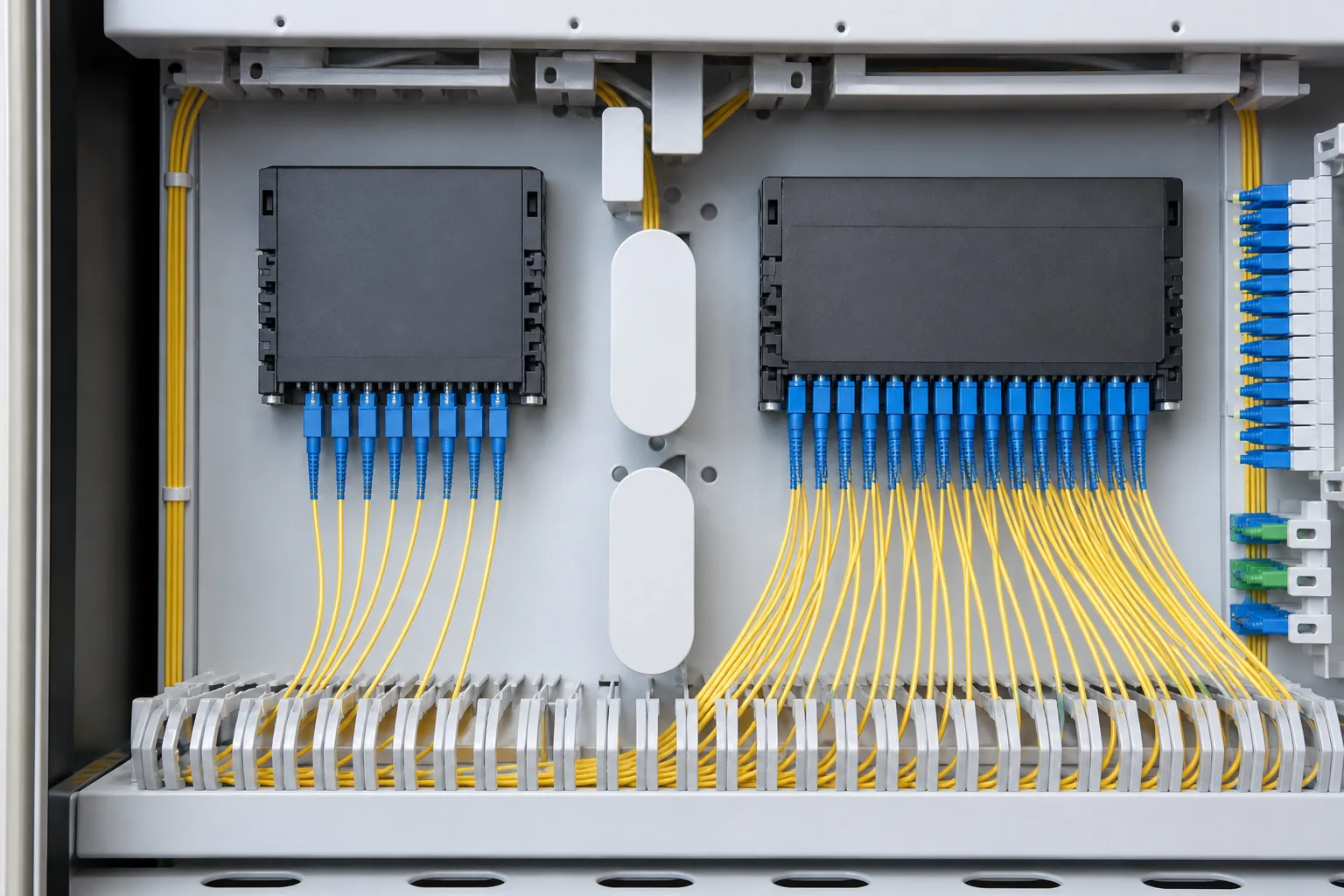
What Is PLC Splitter Loss?
A PLC (Planar Lightwave Circuit) splitter divides an incoming optical signal into multiple output paths. The splitting process inherently introduces loss because the light energy is distributed among the output ports. This loss is expressed in decibels (dB) and includes both the theoretical splitting loss and excess loss from imperfections in the waveguide.
For a 1×N splitter, the theoretical splitting loss is calculated as 10 × log10(N). For a 1×8 splitter, that is 10 × log10(8) ≈ 9.03 dB. For a 1×16, it is 10 × log10(16) ≈ 12.04 dB. In practice, additional excess loss (typically 0.5–1.5 dB) brings the typical insertion loss to around 10.5 dB for 1×8 and 13.5 dB for 1×16, as specified by manufacturers.
It is important to distinguish between insertion loss and other loss parameters like return loss and polarization-dependent loss (PDL). Insertion loss is the primary metric for budgeting, while return loss (the amount of light reflected back toward the source) and PDL (the variation in loss with polarization) are secondary but still relevant for high-performance systems.
1×8 vs 1×16: Loss Comparison
The table below summarizes typical loss values for 1×8 and 1×16 PLC splitters. These figures are based on industry-standard measurements and are consistent with typical datasheets from reputable manufacturers.
| Parameter | 1×8 PLC Splitter | 1×16 PLC Splitter |
|---|---|---|
| Theoretical splitting loss | 9.03 dB | 12.04 dB |
| Typical insertion loss | 10.5 dB (max 11.5 dB) | 13.5 dB (max 14.5 dB) |
| Excess loss (typical) | ~1.5 dB | ~1.5 dB |
| Return loss (min) | 50 dB | 50 dB |
| PDL (max) | 0.3 dB | 0.3 dB |
Note: The exact values may vary by manufacturer and package type (e.g., bare fiber, blockless, or with connectors). Always refer to the datasheet for the specific product.
The key takeaway is that a 1×16 splitter adds about 3 dB more loss than a 1×8. In optical terms, 3 dB corresponds to half the power. This means that if you use a 1×16 splitter, the optical power at each output port is half of what you would get with a 1×8, assuming the same input power.
Selection Criteria: When to Choose 1×8 or 1×16
Number of End Users or Endpoints
The most obvious criterion is how many endpoints you need to serve. A 1×8 splitter provides 8 output ports, while a 1×16 provides 16. If you have exactly 8 subscribers or devices, a 1×8 is sufficient. If you have 16, you need a 1×16. However, you might also consider scalability: if you expect to grow from 8 to 16 subscribers, you could install a 1×16 from the start to avoid future rework, but you must ensure your power budget can handle the extra loss.
Optical Power Budget
Your network’s power budget is the total allowable loss between the transmitter and receiver. It includes splitter loss, fiber attenuation, connector losses, and splice losses. The splitter loss is a significant portion. For example, a typical PON system might have a power budget of 28 dB (for Class B+). If you use a 1×16 splitter with 13.5 dB loss, you have only 14.5 dB left for fiber and connectors. With a 1×8, you have 17.5 dB. This can be the deciding factor if your distances are long or you have many splices.
Fiber Distance and Attenuation
Standard single-mode fiber (G.652) has an attenuation of about 0.35 dB/km at 1310 nm and 0.20 dB/km at 1550 nm. If your distribution distances are long, the extra 3 dB from a 1×16 splitter could limit your reach. For example, at 1550 nm, 3 dB corresponds to about 15 km of fiber. So switching from a 1×8 to a 1×16 could cut your reach by 15 km, which is substantial in rural deployments.
Network Architecture and Splitting Strategy
In PON networks, you can use centralized splitting (one splitter at the central office) or distributed splitting (multiple splitters in the field). A 1×8 or 1×16 might be used as the first-level splitter. For example, a 1×4 splitter feeding four 1×8 splitters yields 32 endpoints. In such designs, the choice of splitter ratio at each stage affects the overall loss. A common practice is to use a 1×8 as the final stage to keep loss lower, but sometimes 1×16 is necessary to serve more users with fewer fibers.
Design Tradeoffs: Power Budget, Distance, and Splitting
Power Budget Calculation Example
Let’s illustrate with a simple power budget calculation. Assume a transmitter output power of +3 dBm, a receiver sensitivity of -25 dBm, and a system margin of 2 dB. The total available loss is 3 – (-25) – 2 = 26 dB.
- With a 1×8 splitter (10.5 dB loss), remaining loss for fiber and connectors: 26 – 10.5 = 15.5 dB.
- With a 1×16 splitter (13.5 dB loss), remaining loss: 26 – 13.5 = 12.5 dB.
If you have 2 connector pairs (0.5 dB each) and 10 splices (0.1 dB each), that’s 1.0 + 1.0 = 2.0 dB. So with a 1×8, you can have 13.5 dB for fiber, which at 0.20 dB/km (1550 nm) gives about 67.5 km. With a 1×16, you have 10.5 dB for fiber, giving about 52.5 km. That’s a 15 km difference—significant for long-reach applications.
Tradeoff Between Split Ratio and Reach
The fundamental tradeoff is between the number of users and the reach. A higher split ratio (1×16 vs 1×8) allows you to serve more users with the same number of feeder fibers, but it reduces the maximum distance. This is a classic engineering tradeoff that must be evaluated against your network’s geographical distribution.
Impact on Optical Signal-to-Noise Ratio (OSNR)
In WDM systems, a higher splitter loss also reduces the OSNR, which can affect system performance. While PON systems are less sensitive to OSNR than long-haul coherent systems, it is still a consideration if you are planning to use multiple wavelengths (e.g., XGS-PON with 10 Gbps). The extra 3 dB loss can degrade the signal quality, especially if the system is already near its sensitivity limit.
Installation Implications: Space, Connectors, and Handling
Physical Size and Mounting
1×16 splitters are physically larger than 1×8 splitters. They may require more space in an optical distribution frame or a splice closure. If you are installing in a compact enclosure, a 1×8 might be the only practical option. Conversely, if you have limited fiber count, a 1×16 can consolidate two 1×8s into one unit, saving space in the long run.
Connector Types and Pigtail Length
PLC splitters come with various connector types (SC, LC, etc.) and pigtail lengths. The choice of connectors affects the overall insertion loss (each connector adds about 0.3 dB). For a 1×16, you have 16 output pigtails, which can be cumbersome to manage. Ensure that the enclosure has adequate cable management to avoid excessive bending and stress on the fibers.
Handling and Storage
Fiber handling is critical. PLC splitters are sensitive to bending and stress. Always follow the manufacturer’s instructions for minimum bend radius. For a 1×16, the fiber count is double, so more care is needed to keep the fibers organized and free from strain. Using proper splice trays and cable ties can prevent micro-bends that increase loss.
Testing and Quality Considerations
Insertion Loss Testing
Before installation, every splitter should be tested for insertion loss and return loss. The Fiber Optic Association (FOA) provides guidelines for testing methods. Use an optical power meter and light source to verify that each port’s loss is within the specified range. For a 1×16, it is especially important to test all 16 ports because the uniformity can vary.
Uniformity and Port-to-Port Variation
Uniformity refers to the maximum difference in insertion loss among the output ports. For a good PLC splitter, this should be less than 1.5 dB. Poor uniformity can cause some subscribers to have much weaker signals than others. Always check the datasheet for uniformity specifications and test for it if possible.
Environmental and Reliability Testing
PLC splitters should meet Telcordia GR-1221 or similar standards for environmental reliability. This includes temperature cycling, humidity, and mechanical stress tests. When sourcing from a manufacturer, ask for test reports and certifications. A reputable supplier will have their products tested by independent labs.
For fiber standards, the ITU-T G.652 recommendation covers single-mode fiber characteristics, and ITU-T G.657 covers bend-insensitive fiber. These standards are relevant to the fiber used in your network and the pigtails of the splitter.
Common Mistakes in Splitter Selection
- Ignoring the power budget: Choosing a 1×16 when your budget cannot accommodate the extra 3 dB loss, leading to marginal link performance.
- Overlooking uniformity: Assuming all ports have the same loss. In reality, port-to-port variation can be significant, especially in low-cost splitters.
- Not considering future scalability: Installing a 1×8 when you know you will soon need 16 endpoints, forcing a costly re-split.
- Poor fiber management: With a 1×16, the increased fiber count can lead to bending and stress if not managed properly, increasing loss beyond specifications.
- Skipping testing: Not testing splitters before installation, which can lead to unexpected network failures.
Procurement Checklist
When buying PLC splitters, use this checklist to ensure you get the right product:
- Specify the split ratio (1×8 or 1×16) and the number of output ports.
- Check the insertion loss and uniformity specifications against your power budget.
- Choose the correct package type (bare fiber, blockless, with connectors, etc.) for your installation.
- Verify the operating wavelength range (typically 1260–1650 nm for PON).
- Ensure compliance with relevant standards (e.g., IEC 61753-1, IEC 61753-2).
- Request test reports and quality certifications from the manufacturer.
- Consider the connector type and pigtail length to match your network components.
- Evaluate the supplier’s quality management system—see our quality page for more details.
Conclusion
Choosing between a 1×8 and a 1×16 PLC splitter is a critical decision that affects your network’s reach, scalability, and cost. The 1×8 offers lower loss (about 10.5 dB) and is suitable for shorter distances or higher power budgets, while the 1×16 provides more endpoints but adds 3 dB of loss, reducing your reach by roughly 15 km at 1550 nm. Use a power budget analysis to determine which splitter fits your network. Always consider uniformity, testing, and quality. For high-quality PLC splitters, explore our PLC splitter product line. If you need assistance with your specific network design, contact our engineering team for expert guidance.
Frequently Asked Questions
What is the typical insertion loss for a 1×8 PLC splitter?
A 1×8 PLC splitter typically has an insertion loss of about 10.5 dB, with a maximum of around 11.5 dB, depending on the manufacturer and package type.
How much loss does a 1×16 PLC splitter add compared to a 1×8?
A 1×16 PLC splitter typically adds about 3 dB more loss than a 1×8. This is because the theoretical splitting loss increases from 9.03 dB to 12.04 dB, and the typical insertion loss goes from 10.5 dB to 13.5 dB.
Can I use a 1×16 splitter in a PON network with a 28 dB power budget?
Yes, you can, but you must account for the 13.5 dB splitter loss, leaving about 14.5 dB for fiber, connectors, and splices. This may limit your reach compared to using a 1×8, which would leave 17.5 dB.
What is uniformity in a PLC splitter and why does it matter?
Uniformity is the maximum difference in insertion loss between the output ports of a splitter. It matters because poor uniformity can cause some subscribers to receive much weaker signals than others, leading to performance issues. A good uniformity is typically less than 1.5 dB.
Should I choose a 1×8 or a 1×16 splitter for future scalability?
If you expect to grow from 8 to 16 endpoints, you might choose a 1×16 from the start to avoid rework. However, you must ensure that your power budget can handle the extra 3 dB loss. If your distances are long, a 1×8 might be safer, and you can add another splitter later.
How can I test a PLC splitter before installation?
You can test a PLC splitter using an optical power meter and light source. Measure the insertion loss on each port and compare it to the datasheet. Also check return loss and uniformity. The FOA provides guidelines for testing procedures.
What are the main differences between 1×8 and 1×16 PLC splitters in terms of installation?
A 1×16 splitter is physically larger and has more output pigtails, requiring more space and careful fiber management. The connectors and pigtail lengths also affect installation. Ensure your enclosure can accommodate the extra fibers without bending them beyond the minimum bend radius.
Complete topic guide: PLC Fiber Splitters: Complete Design and Selection Guide.







