
When most people think of fiber optics, they imagine data centers, telecom networks, or undersea cables. But a new generation of engineers is deploying optical fiber in one of the most unforgiving environments on Earth: glaciers. A recent report in Optics & Photonics News highlights how an optical-fiber probe is being used to monitor glacial crevasses in real time. Beyond the headline, this application offers a masterclass in distributed sensing, cable robustness, and the importance of specifying the right fiber for extreme conditions.
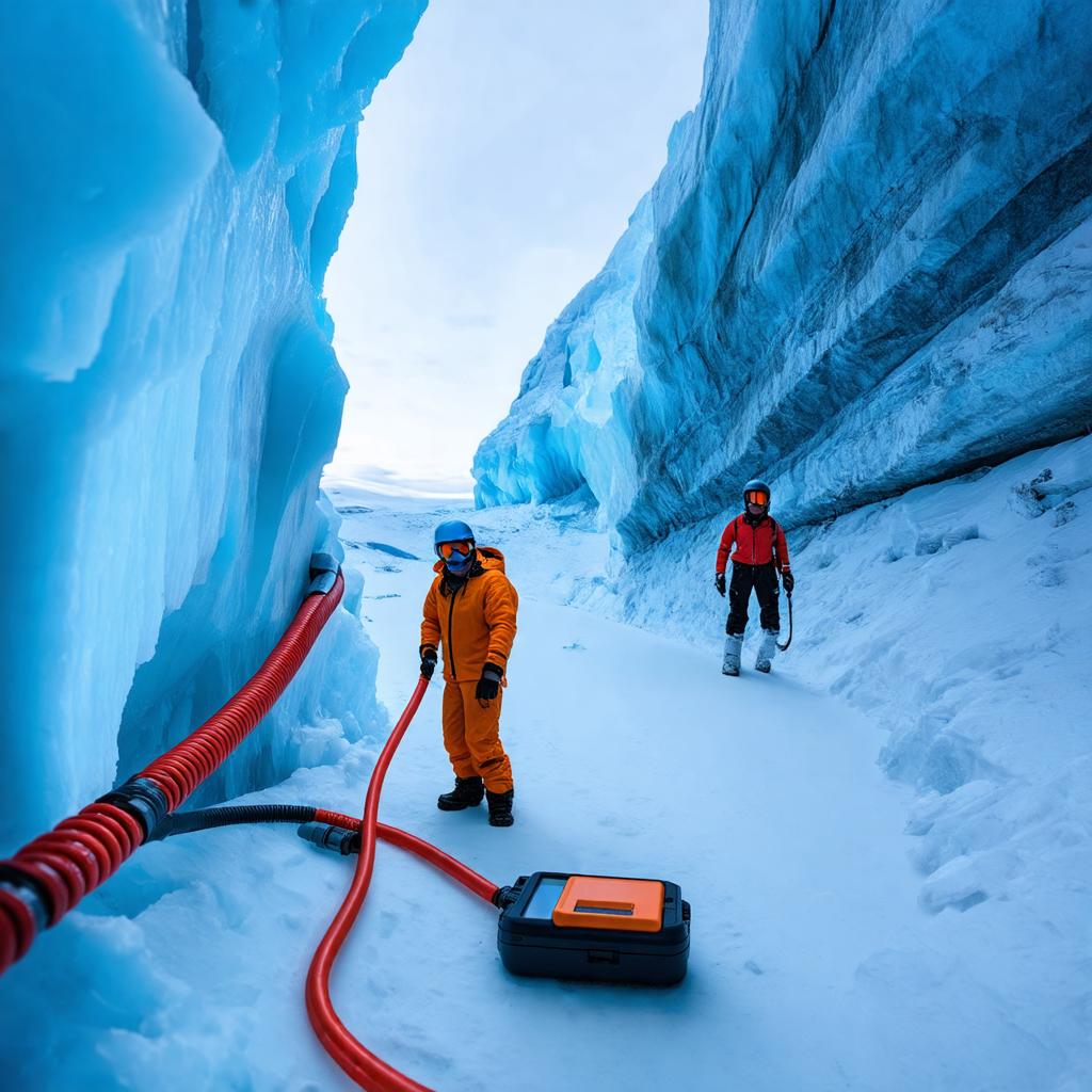
For procurement professionals and network designers, the technology behind glacial monitoring is not just academic. It reveals how distributed fiber-optic sensing (DFOS) works, why certain cable designs matter, and how to choose components that survive temperature swings, mechanical stress, and moisture. This article explains the engineering behind the probe, compares it to conventional sensing, and translates those lessons into practical buying decisions.
What Is Distributed Fiber-Optic Sensing and How Does It Work?
Distributed fiber-optic sensing uses the entire length of an optical fiber as a continuous sensor. Unlike point sensors that measure at discrete locations, DFOS turns a standard telecom-grade fiber into thousands of virtual sensors, often spaced every meter or less. The technique relies on analyzing light that is backscattered within the fiber as a laser pulse travels along it.
Three primary backscattering mechanisms are exploited:
- Rayleigh scattering – caused by microscopic density fluctuations; used for distributed acoustic sensing (DAS) and vibration detection.
- Raman scattering – temperature-dependent; used for distributed temperature sensing (DTS).
- Brillouin scattering – sensitive to both temperature and strain; used for distributed strain sensing (DSS).
By measuring the time-of-flight and the spectral characteristics of the returned light, an interrogator can map temperature, strain, or acoustic events along the fiber. In glaciology, a fiber embedded in or lowered into a crevasse can detect strain changes, micro-cracks, and the movement of ice, providing early warning of crevasse expansion or collapse.
Why Optical Fiber Is Ideal for Glacial Monitoring
Glaciers present extreme conditions: sub-zero temperatures, high humidity, ice melt, and physical abrasion from moving ice. Electronic sensors often fail in such environments due to corrosion, power limitations, and electromagnetic interference. Optical fiber, in contrast, is passive, immune to EMI, and can be made rugged with proper cabling. It also allows for long-distance sensing—tens of kilometers—without the need for power at the sensing point, which is a huge advantage in remote polar regions.
Engineering the Probe: Cable Design and Deployment
The optical-fiber probe described in the news is not just a bare fiber dropped into a crevasse. It is a carefully engineered assembly. Key design considerations include:
- Mechanical protection: A stainless-steel or polyimide-coated fiber may be used to resist abrasion and crushing.
- Temperature range: The cable must operate at temperatures as low as -40°C or lower, which affects the choice of jacketing materials.
- Water blocking: Glacial meltwater can ingress into cables, so water-blocking gels or tapes are essential.
- Strain transfer: For strain sensing, the fiber must be mechanically coupled to the ice or structure, so a tight-buffered or specially bonded cable is preferred.
- Deployment method: The probe may be lowered into a borehole or embedded in ice, requiring careful handling to avoid microbends.
These requirements mirror those of industrial fiber installations in pipelines, power cables, and structural health monitoring. The lesson for buyers is that not all fiber cables are created equal; harsh environments demand specialized designs.
From Glacier to Data Center: Common Sensing Principles
While a glacial probe might seem far removed from a data center, both rely on the same fundamental physics. In fact, the OTDR (Optical Time-Domain Reflectometer) used to test fiber links works on Rayleigh backscatter, the same principle behind DAS. This means that the skills and equipment used for fiber installation and maintenance are directly applicable to understanding distributed sensing.
For example, an engineer troubleshooting a fiber link with an OTDR is essentially measuring backscatter amplitude along the fiber. A DAS interrogator does the same but at much higher sensitivity and sampling rates, detecting acoustic disturbances. Understanding this connection helps engineers appreciate why fiber quality—such as attenuation uniformity and splice loss—is critical for sensing applications. A poorly spliced fiber with high loss will degrade sensing performance just as it would degrade data transmission.
Selection Criteria for Fiber in Harsh Environments
If your project involves outdoor, industrial, or extreme-environment fiber deployment, consider the following specification parameters. The table below summarizes typical options and what they mean for performance.
| Parameter | Standard Telecom Grade | Harsh Environment Grade | Engineering Consideration |
|---|---|---|---|
| Operating Temperature | -10°C to +70°C | -40°C to +85°C | Low-temperature jacketing prevents cracking; high-temperature prevents softening. |
| Water Blocking | None or basic | Water-blocking gel or tape | Prevents hydrogen darkening and microbend loss from ice formation. |
| Crush Resistance | Typically 100 N/cm | Up to 220 N/cm or higher | Protects against ice movement, machinery, or human traffic. |
| Flexibility | Standard bend radius | Reduced bend radius (e.g., G.657.A2) | Allows tighter routing in confined spaces without excess loss. |
| Jacket Material | PVC or LSZH | TPU, HDPE, or stainless steel armor | UV resistance, abrasion resistance, chemical resistance. |
| Fiber Type | G.652.D | G.657.A1 or A2 | Bend-insensitive fiber reduces loss when kinked or under strain. |
For sensing applications, you may also need to specify the fiber’s attenuation uniformity and backscatter coefficient. These are not standard telecom specifications, so it is essential to communicate your sensing requirements to your supplier.
Standards and Testing: What to Demand from Your Supplier
When procuring fiber for harsh environments, always reference applicable standards. The International Electrotechnical Commission (IEC) and the International Telecommunication Union (ITU) provide the most relevant guidelines:
- IEC 60794 – Optical fibre cables. This standard family covers mechanical, environmental, and electrical tests for cables. Look for specific tests like crush resistance, impact, and temperature cycling.
- ITU-T G.657 – Characteristics of a bending-loss insensitive single-mode optical fibre and cable. This is key for tight-bend applications.
- ITU-T G.652 – Characteristics of a single-mode optical fibre and cable. The baseline for standard single-mode fiber.
For sensing cables, also consider IEC 60794-5 for optical fibre cables for microduct installation, which may include additional robustness tests. Always request the test reports for the specific cable lot you are purchasing. A reputable supplier will provide them.
Practical Takeaways for Fiber-Optic Buyers
The glacial probe story is a reminder that fiber optics are more than just data pipes. They are versatile sensors. If your project involves any kind of environmental monitoring, structural health, or extreme conditions, here are actionable steps:
- Assess the environment: Document temperature range, moisture exposure, mechanical stress, and installation method.
- Specify the right fiber: Choose bend-insensitive fiber (G.657.A2) for tight spaces and consider the attenuation and backscatter uniformity for sensing.
- Demand robust cable construction: Look for water-blocking, armoring, and appropriate jacketing materials.
- Verify standards compliance: Ask for IEC/ITU test reports and inspect the cable for quality marks.
- Test before deployment: Use an OTDR to verify continuity and loss, and if possible, perform a pre-deployment sensing test.
Whether you are building a glacial monitoring network or a fiber optic products wholesale supply chain, the principles remain the same: match the product to the environment, verify quality, and test thoroughly.
For more information on selecting the right fiber and cable for your application, explore our optical fiber and fiber optic cable categories, or contact our engineers for expert guidance.
Frequently Asked Questions
How should glacier monitoring choose between DAS, DTS and strain sensing?
Start with the observable: acoustic or dynamic events, distributed temperature, or strain. Then qualify the interrogator and cable together for spatial resolution, sampling interval, temperature range and mechanical coupling; telecom suitability alone does not establish sensing performance.
What should a glacier cable deployment record before installation?
Record the sensing objective, cable construction, required coupling or isolation, expected movement, retrieval constraints and baseline optical measurements. Test the selected cable and termination arrangement under the project conditions rather than assuming a universal sensing distance.
Related: Fiber Optic Outage Prevention: Lessons from a Wyoming Network Failure







