
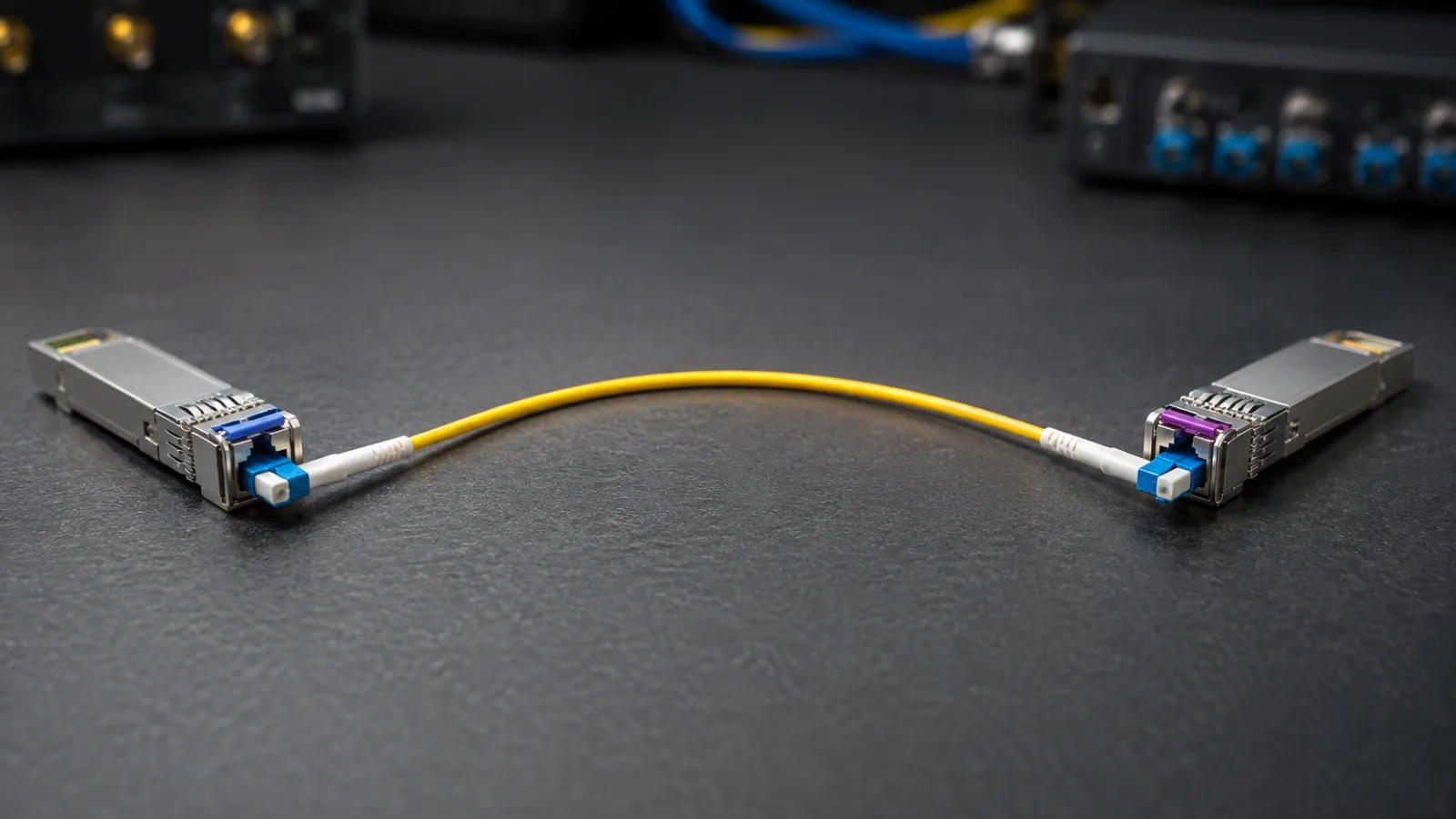
Summary: To understand how to pair single fiber BiDi SFP modules, start with four values: the transmit and receive wavelength bands at both endpoints. End A must transmit into End B’s receive band, and End B must transmit into End A’s receive band. Then verify line rate, host support, connector compatibility and optical margin in both directions. A shared reach label or matching latch color is insufficient.
Single-fiber bidirectional optics are useful when spare strands are scarce or an existing duplex circuit needs to release one strand. The saving comes with a different inventory requirement: the two ends may need complementary parts. This guide provides a purchase matrix and a commissioning worksheet for that specific problem.
Build the wavelength matrix before ordering
As a documented example, Cisco’s Gigabit Ethernet SFP datasheet describes BX10-U transmitting at 1310 nm and receiving at 1490 nm, with BX10-D doing the reverse. These values describe that example family; other BiDi families use other bands and operating conditions.
| Endpoint | Example transmit wavelength | Example receive wavelength | Required opposite endpoint |
|---|---|---|---|
| U side | 1310 nm | 1490 nm | D side receiving 1310 nm |
| D side | 1490 nm | 1310 nm | U side receiving 1490 nm |
Place the complete supplier part number beside every row. Nominal wavelengths are a starting point; the specified transmit range must be compatible with the far receiver’s acceptance range. Do not infer that two products interoperate simply because both are marketed as “BiDi,” “single strand,” or “10 km.”
Keep protocol and host checks separate
Matching wavelengths cannot fix a line-rate mismatch. Verify Ethernet speed, supported operating mode, any required FEC setting, electrical host interface and platform software compatibility. An SFP-shaped device is not evidence that every port supports its signaling. Obtain the switch or router vendor’s compatibility confirmation for the exact hardware and software combination.
The FOA network specification overview lists several optical applications, including single-fiber bidirectional families at different speeds. Its value here is the reminder that “fiber Ethernet” covers multiple physical interfaces. Treat the chosen application designation as a procurement field, not an optional description.
One physical strand still needs two optical checks
The glass path is shared, but its attenuation can differ with wavelength. The transmitters and receivers may also have different guaranteed values. Build separate A-to-B and B-to-A worksheets, even when the two module cases look identical. The weaker direction determines whether the pair meets the required service margin.
Use minimum transmitter power for the low-power check and maximum transmitter power for the overload check. Include the whole deployed path: patch cords, mated connector pairs, splices, passive filters and any intentional attenuation. Avoid counting the same connector twice if it is already included in an assembly’s specified insertion loss.
Worked example: an 8 km single-fiber route
These are illustrative engineering inputs, not specifications for the Cisco example or a Liqiba product. Assume an 8 km single-mode route, four mated connections at 0.30 dB each, six splices at 0.10 dB each and a 2.0 dB planning reserve. Assume fiber attenuation of 0.35 dB/km in one direction’s wavelength band and 0.25 dB/km in the other.
| Item | A to B | B to A |
|---|---|---|
| Fiber loss | 8 × 0.35 = 2.80 dB | 8 × 0.25 = 2.00 dB |
| Connections | 4 × 0.30 = 1.20 dB | 1.20 dB |
| Splices | 6 × 0.10 = 0.60 dB | 0.60 dB |
| Planning reserve | 2.00 dB | 2.00 dB |
| Total required budget | 6.60 dB | 5.80 dB |
If a hypothetical module pair guarantees a minimum launch of −8 dBm and a receiver sensitivity of −19 dBm in each direction, its simplified power budget is 11 dB. The remaining allowance after the stated reserve is therefore 4.4 dB A-to-B and 5.2 dB B-to-A. Replace every assumption with the actual component limits before purchase.
This calculation screens power feasibility only. It does not validate dispersion, reflection tolerance or application reach. It also says nothing about overload: that second calculation needs the maximum launch and minimum actual path loss, excluding the reserve as though it were physical attenuation.
Specify the patching path precisely
Check single-mode fiber category, connector size and polish at each interface. An LC connector name alone does not distinguish all mating requirements. Do not directly mate APC and UPC interfaces. If a route includes different connector types, specify an appropriate hybrid assembly with compatible polish at each individual connection.
Our simplex versus duplex patch-cord guide explains the physical arrangement, while the fiber patch-cord selection guide covers the broader selection process. For quotations, use the fiber optic patch cords and assemblies page and provide both endpoint interfaces, length, fiber type and required test records.
A purchase record that prevents mixed pairs
Create one line item per endpoint rather than ordering an undifferentiated quantity of modules. Record the site, device, port, full part number, transmit band, receive band, line rate, temperature rating and firmware requirement. Add a pair identifier linking the two line items. This is particularly useful when a warehouse stocks several reach classes.
Keep replacement inventory complementary too. If twelve links use twelve U units and twelve D units, stocking two spare U units does not cover a D-side failure. Select the spare mix from the installed population and restoration policy. Clearly label the endpoint role on the package without relying on removable dust-cap colors.
Review three common replacement scenarios
A failed far-end module: identify its role from the saved wavelength matrix before ordering. If the surviving unit transmits in one band and receives in another, the replacement must complement both bands. Obtain written compatibility for the actual pair when substituting a vendor or product family. A same-day replacement with the wrong receiving band can leave good fiber appearing defective.
A migration from duplex optics: identify which of the existing two strands will carry the new service. Verify that strand in both relevant wavelength conditions and update the patch-panel record. Remove any obsolete cross-connect assumptions from the work order. The released strand can become reserve only after its endpoint identity and condition are established.
A speed upgrade: review both endpoints together. A higher-rate module may have a different wavelength pair, reach specification or host requirement. Budget the work as an interface change, including a rollback plan and the old paired inventory. Keeping the original cable does not mean the existing optical acceptance evidence covers the new application.
Record the pair as one service asset
A useful handover row contains the pair identifier, both device ports, both module serial numbers, the fiber strand, each transmit and receive band, directional loss results and the date of the traffic test. Add the approved spare part for each side. This record lets a technician replace an endpoint without reconstructing the design from packaging or an old purchase order.
If several services share a passive wavelength system, extend the row to include the exact filters and port assignments. Do not assume a standalone single-fiber pair can be inserted into an existing wavelength plan without checking passbands, isolation and optical penalties.
Commissioning and fault isolation
Before connecting the active optics
Confirm continuity to the intended far-end strand, inspect and clean interfaces, and verify loss using equipment appropriate to the required wavelengths and test method. Preserve the strand identifier from the patch panel to the equipment port. An unused neighboring fiber is not automatically the documented counterpart.
After the link comes up
Record receive power at both ends, module identity, link status and error counters during an agreed traffic test. Where available, digital optical monitoring helps compare operating readings over time, but it does not replace the instrument and acceptance procedure required by the project. Investigate asymmetry against the directional budget.
If the link stays down, review pair identity, wavelength compatibility, host recognition and port settings before changing the fiber plant. If it comes up but errors increase, examine power, reflections, connectors and platform counters. Save the final endpoint matrix with the test report so that a later replacement follows the same verified combination.
Frequently Asked Questions
Can two identical BiDi modules connect to each other?
For the complementary single-fiber optics discussed here, usually not. One end must transmit in the wavelength band accepted by the other receiver, and vice versa. Verify both complete part numbers rather than relying on similar labels.
Do A/B or U/D labels guarantee compatibility?
No. Those labels are useful only within a documented product family. Compare transmit and receive bands, line rate, reach class, optical power specifications and host support.
Can I use one strand from a duplex cable?
Yes, if the selected strand and its termination meet the BiDi module requirements. Document the strand end to end and protect the unused strand; a duplex connector clip may need an approved simplex arrangement.
Does a 10 km module guarantee service on any 10 km route?
No. Reach also depends on optical loss, dispersion and the specific module application limits. Check both directions using the documented wavelength bands and installed-path measurements.
Is a BiDi link automatically compatible with GPON?
No. Sharing one fiber does not make protocols interchangeable. Point-to-point Ethernet BiDi optics and a PON OLT/ONT system have different signaling and access requirements.







