
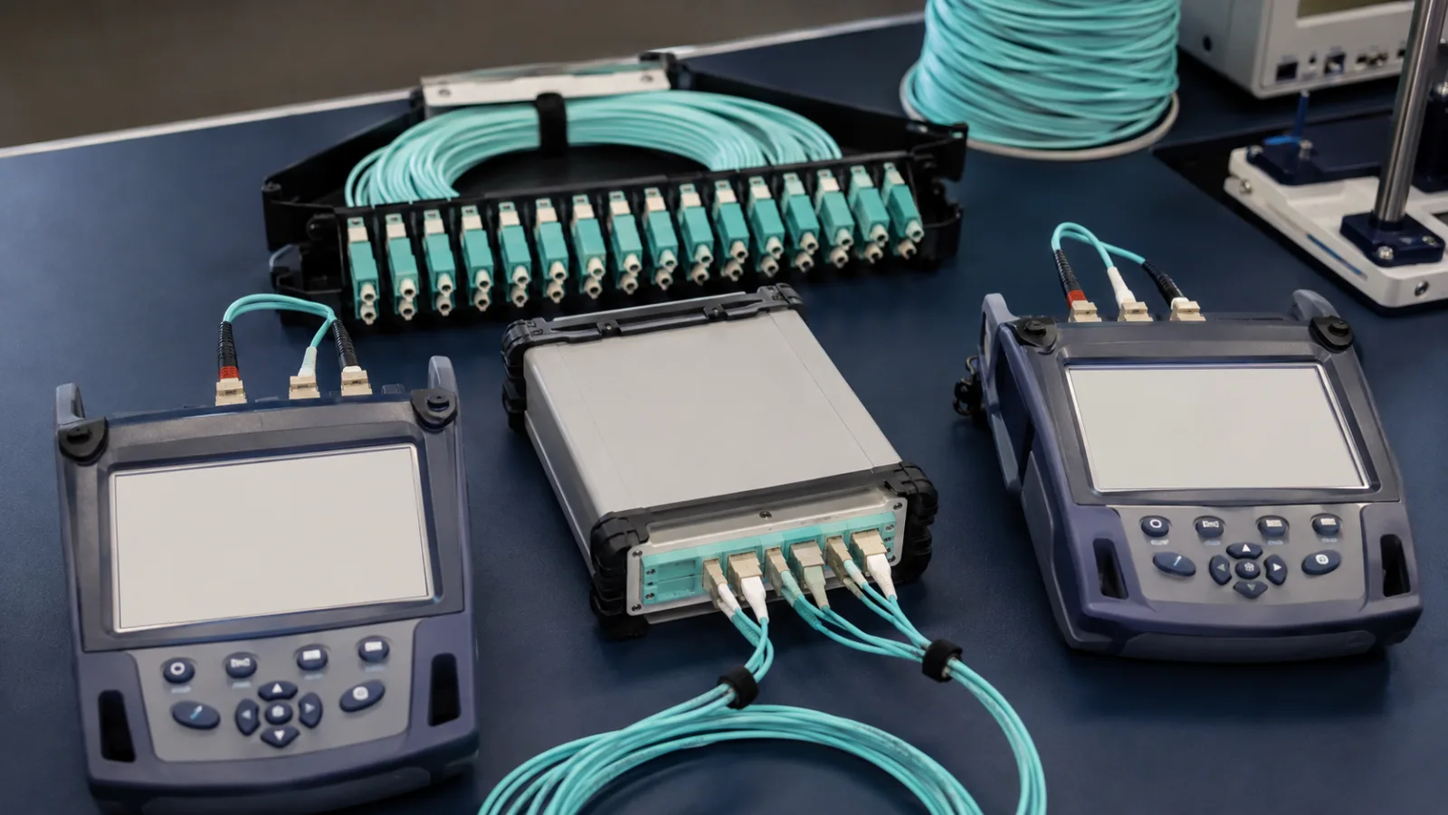
Summary: Correct encircled flux launch conditions for OM4 testing help make attenuation measurements comparable by controlling the multimode light distribution delivered into the test path. EF is a property of a defined launch configuration. It is not established simply by using an aqua cord, selecting OM4 on a screen or winding any jumper around a mandrel.
A commissioning disagreement often begins with two testers reporting different loss on the same link. Before replacing the installed cable, confirm that both teams used equivalent launch conditions, reference methods and acceptance boundaries. This guide provides a record structure and an original near-limit example for that review.
Why the distribution of launched light matters
Multimode fiber supports many propagation modes. A source can deliver different proportions of power into those modes, and connections or bends may affect them differently. Consequently, two sources can produce different measured attenuation through the same physical cabling even when their total output power is similar.
Fluke Networks’ EF explanation describes the purpose as controlling the launch to reduce disagreements between measurement systems. In conceptual terms, encircled flux describes the fraction of optical power contained within progressively larger radii of the fiber end-face distribution. Formal limits and verification require the applicable specification and qualified equipment.
Apply the correct standard and equipment configuration
IEC 61280-4-1:2019 covers attenuation measurement for installed multimode cabling, including OM4, and addresses encircled flux and measurement uncertainty. Use the edition and amendments required by the project and the equipment’s supported implementation. The publication summary is background, not a substitute for the complete standard.
An EF statement must identify where compliance is established. Some equipment controls the output together with a specified cord or conditioning assembly. For example, VIAVI’s explanation of its Certifier EF arrangement describes a controlled output and a modally transparent launch cord. That implementation illustrates why changing an apparently minor accessory can affect the qualified configuration.
Keep three independent controls in view
| Control | What it establishes | What it cannot establish alone |
|---|---|---|
| Launch condition | Specified multimode power distribution at the defined interface | The correct zero-loss reference |
| Reference procedure | Baseline and included connection boundaries | Cleanliness and suitability of every subsequent mating |
| Cord and connector verification | Known condition of the measurement path | The installed link’s final compliance |
A stable reference does not prove that the launch is compliant. A compliant launch does not excuse a contaminated receive cord. Treat each control as a separate field in the record so that a later investigation can isolate what changed.
Worked example: a result close to a project limit
Assume a fictional installed-link specification permits 1.50 dB at the stated wavelength and reference boundary. Team A reports 1.32 dB; Team B reports 1.61 dB. These numbers are hypothetical and are not measurements from Liqiba or a named tester.
| Result | Reading | Arithmetic margin to 1.50 dB |
|---|---|---|
| Team A | 1.32 dB | +0.18 dB |
| Team B | 1.61 dB | −0.11 dB |
| Difference between readings | 0.29 dB | Requires investigation |
The difference alone does not prove an EF fault. It could reflect reference topology, dirty connectors, wavelength settings or a changed link. First compare the recorded configurations. Recreate the approved setup and verify the cords before repeating the measurement on the identified fiber.
Suppose the controlled repeat is 1.43 dB and the project separately specifies a 0.10 dB conservative guard-band decision rule. The assessed value would be 1.43 + 0.10 = 1.53 dB, so the result would not qualify under that particular rule. The 0.10 dB allowance is an assumed project policy, not a universal EF or IEC requirement.
This example separates measured loss from the acceptance decision. Define the rule before testing, and avoid repeatedly remating until a favorable number appears. Retain the original results and record the cause of any justified retest.
A launch-configuration checklist for the job folder
Source and conditioning
Record tester model, module identity, firmware, wavelengths and the manufacturer-approved conditioning arrangement. Keep the compatibility statement or instructions with the job. Confirm whether the EF condition applies at the instrument port, after a specified launch cord or at another defined reference plane.
Launch and receive cords
Record part numbers, fiber category, lengths, connector types and verification results. Inspect both mating surfaces and follow the prescribed cleaning process. A cord that has been repaired or substituted needs review against the approved configuration; visual similarity does not demonstrate equivalent modal behavior.
Reference and test boundary
Record the reference method, reference time and connections included or excluded. Draw the reference arrangement and the actual test arrangement where they differ. Changing the source-side connection may invalidate the established reference; follow the tester instructions before continuing after an interruption.
Installed-link identity
Record the exact panel ports, strand, direction, wavelength and applicable loss limit. Ensure that the second team tests the same boundary. A permanent-link result and a channel result containing additional equipment cords are not directly interchangeable merely because both refer to the same rack pair.
Why a generic mandrel is not a universal solution
A mandrel can alter modal content by bending the launch fiber, but its effect depends on the fiber construction, wavelength and geometry. Bend-insensitive fiber is specifically designed to respond differently to bending. Use a prescribed and qualified setup rather than choosing a convenient cylindrical object and assuming compliance.
Do not introduce tight bends into an otherwise qualified test arrangement to make its readings resemble another instrument. Such adjustments can change the reference and obscure the original issue. If the approved equipment requires a particular conditioning accessory, treat it as part of the measurement system.
A practical comparison exercise for two test teams
Choose a clearly identified control link and freeze its physical patching. Have both teams record their complete approved configurations before making changes. Check wavelength, reference method, connection boundaries and cord verification first. This avoids attributing every disagreement to the light source when the two tests may include different components.
Record a short series of measurements using a predefined remating procedure rather than an unlimited search for the best value. Keep the full series, the range and any observed connector condition changes. The series can reveal instability, but its average does not replace the specified pass/fail method or establish EF compliance by itself.
Assign responsibility for configuration changes
Designate who can approve a substitute reference cord, firmware change or different conditioning accessory. Require a new configuration record and the verification steps called for by the manufacturer. Without this control, a correct morning setup can become an undocumented afternoon setup after a damaged cord is replaced.
For a recurring project, retain one approved configuration sheet with the job template and update it when equipment changes. Include the accepted reference-plane drawing and the decision rule. This gives different crews a common procedure while preserving the equipment-specific instructions needed to implement it correctly.
If the comparison remains unresolved, preserve both data sets and ask the responsible test-equipment suppliers to review them. Provide the raw files and configuration details rather than only the final pass/fail screenshots. That evidence supports a technical investigation without assuming that the lower reading is automatically correct.
Procurement and handover requirements
For the commercial fiber optic patch cords and assemblies page, specify whether you need ordinary operational jumpers or cords intended for a qualified test setup. Include the tester model and manufacturer’s exact cord requirements. An OM4 assembly can be suitable for a live link without being approved as that tester’s reference cord.
The OM3, OM4 and OM5 comparison explains fiber-category selection, while the installation and testing guide provides overall commissioning context. Keep this launch-condition record attached to the accepted results so future tests can reproduce the original setup.
The final deliverable should include the configuration, reference verification, original measurement files and the agreed decision rule. Passing attenuation under controlled launch conditions provides useful loss evidence; it does not independently certify bandwidth or guarantee every higher-speed application. Those checks remain tied to the selected cabling and active interface specifications.
Frequently Asked Questions
Does an OM4 label on the cord prove an EF-compliant launch?
No. OM4 identifies a fiber category, while EF describes the launch power distribution. Verify the complete source, conditioning and reference-cord configuration at the specified output interface and wavelengths.
Can a mandrel wrap always replace EF conditioning?
No. Mandrel effects depend on fiber construction, wavelength and the prescribed setup. Follow the qualified instrument configuration rather than assuming a generic diameter and number of turns establishes EF compliance.
Does EF replace setting an optical power reference?
No. EF controls how power is distributed across the multimode launch. Referencing establishes the baseline used for insertion-loss comparison. Both must be correct.
Can I average a pass and a fail from two testers?
Not to establish compliance without an agreed method. First reconcile launch conditions, reference boundaries, cord verification and test limits. Averaging incompatible measurements can hide the reason they disagree.
Does passing an EF loss test certify all OM4 bandwidth properties?
No. An attenuation test measures loss under specified conditions. It does not independently certify modal bandwidth, every application reach, or the performance of the active equipment.







