
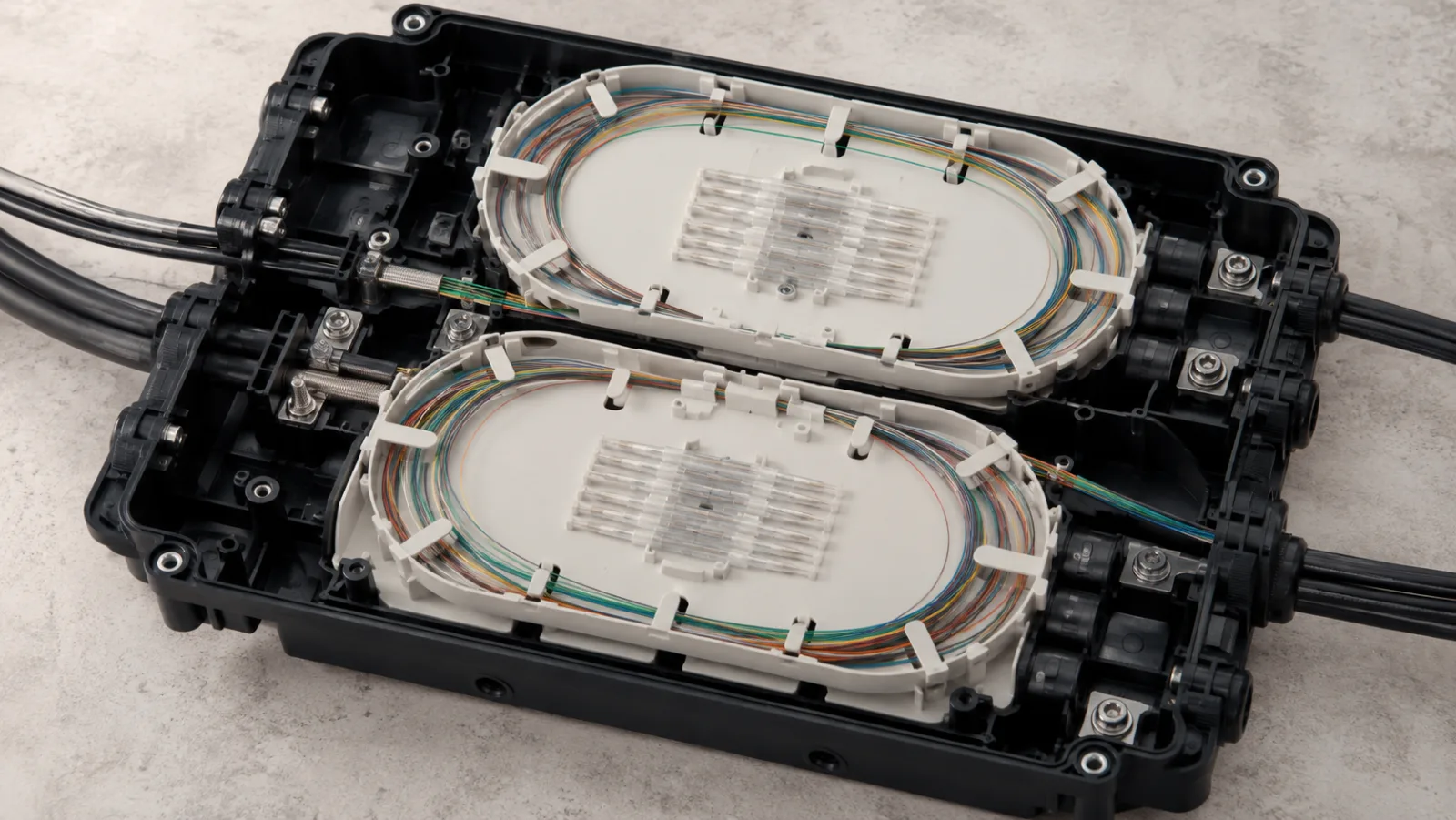
Summary: To establish how to calculate fiber splice tray capacity, count the joints that must be stored, identify the approved protection sleeves and allocate circuits before dividing by a headline fiber rating. A closure may have enough theoretical slots and still be unsuitable because of segregation rules, slack storage or cable-entry constraints.
This guide provides a capacity worksheet for a hypothetical branching location. It separates the arithmetic minimum from the installed arrangement a technician can safely maintain. The objective is a reproducible bill of materials, not the maximum number of fibers that can be physically squeezed into a tray.
Count joints, fibers and sleeves separately
For individual fusion splicing, one joint normally needs one approved protection sleeve. For mass-fusion ribbon work, one sleeve can protect several fiber joints, but the tray and sleeve arrangement must support that construction. The words “splice capacity” can therefore refer to different units in different documents.
CommScope’s NG4 tray specification illustrates this distinction with separate single-fusion and ribbon configurations. That product example does not establish the capacity of an unrelated closure. Use its distinction between configurations, not its numerical rating, when reviewing another assembly.
Start from a splice schedule containing incoming cable, tube, fiber, outgoing destination, joint type and sleeve type. Do not count an uncut through-fiber as a splice merely because it enters the closure. It still needs storage and protection, but it consumes a different resource.
Make circuit segregation an explicit rule
Some networks prefer to keep a branch, customer group or service class on a separate tray so maintenance affects fewer unrelated circuits. That policy can increase the tray count compared with a fully mixed arrangement. Decide the policy before approving the enclosure size.
The tray map should identify both occupied positions and reserved positions. A spare slot on a live tray is not necessarily available to a future branch if routing or access rules prohibit mixing. Capacity is usable only when the network’s maintenance policy allows it to be assigned.
Worked example: five operational groups
Assume a fictional closure using approved trays that each store 24 individual fusion sleeves without stacking. The project has five groups containing 28, 20, 16, 8 and 10 joints. All use compatible single-fiber sleeves, and the owner requires each group to remain on separate trays.
| Group | Required joints | Trays when groups remain separate | Unused positions in those trays |
|---|---|---|---|
| Building A | 28 | 2 | 20 |
| Building B | 20 | 1 | 4 |
| Building C | 16 | 1 | 8 |
| Monitoring service | 8 | 1 | 16 |
| Committed future branch | 10 | 1 | 14 |
| Total | 82 | 6 | 62 |
If all joints could be mixed freely, the arithmetic minimum would be ceiling(82 ÷ 24) = four trays. Under the stated segregation rule, the sum of the separate requirements is six trays. If the owner also requires one completely unused reserve tray, the design needs seven installed tray positions.
These numbers describe a planning example, not a named product or customer installation. The 62 empty positions within the six allocated trays remain subject to the group assignments. They should not be advertised as unrestricted expansion capacity while the segregation rule remains in force.
Test a growth scenario
Suppose Building B later needs six more joints, increasing its total from 20 to 26. Its existing 24-position tray no longer suffices. Under the same segregation rule, it needs a second tray even though many positions remain empty elsewhere.
The dedicated reserve can cover that change only if the policy allows it and the physical route to the new tray is suitable. Once used, the enclosure no longer has an unused reserve tray. Update the capacity ledger and decide whether the minimum reserve must be replenished.
Review the sleeve and fiber construction
Record sleeve length, diameter and the approved holder arrangement. A sleeve that can be pushed into a channel is not necessarily qualified for that tray. Do not stack sleeves unless the manufacturer explicitly supports the configuration and provides the corresponding routing instructions.
AFL’s Apex X-3H specifications show how capacity depends on tray and fiber construction, with conditions attached to high-density arrangements. This is a reminder to obtain a complete configuration rather than comparing the largest number printed on two product pages.
For ribbon work, distinguish conventional ribbon from rollable ribbon and verify compatibility with the splicer, protection sleeve, transportation tubing and tray. If ribbon is separated into individual fibers for a particular operation, the capacity calculation and handling procedure may change.
Check resources beyond splice holders
Uncut-fiber and tube storage
A branching closure can contain substantial pass-through fiber that never enters a splice holder. Check the storage basket, tube routing and bend requirements for that material. A low splice count does not guarantee a low storage requirement.
Cable entries and sealing
Count cable entries independently and match each cable’s shape and diameter to the approved seal. A seven-tray arrangement does not help if the required branch cables cannot enter the closure correctly. Include unused-port sealing and future access provisions in the purchase specification.
Access and installation space
Verify that the enclosure can be opened and trays moved in the planned location without loading fibers. Consider available handhole or cabinet space, mounting orientation and service access. The external body dimensions alone do not describe the working envelope needed during maintenance.
Make the tray map maintainable
Assign a permanent tray identifier and position numbers linked to the splice schedule. Record the allocation owner, fiber route and status. Use separate labels for installed-active, installed-reserved, stored-uncut and unavailable capacity so that a technician does not mistake an empty-looking location for an unassigned resource.
Retain a configuration drawing with the closure model, tray part numbers and sleeve specification. If an installer substitutes a component, obtain approval and update the capacity record. An apparently equivalent tray can have a different holder layout or slack requirement.
Plan repairs as well as new connections. A re-splice may consume additional slack and can alter the route within the tray. Confirm that the specified service allowance supports the intended maintenance procedure instead of treating every unoccupied holder as evidence that the tray has spare working capacity.
Audit the completed allocation before closing the enclosure
Reconcile the installed sleeve count with the approved splice schedule, tray by tray. Record any joints moved to a different position and identify why the change was necessary. The physical count should match the documentation without requiring someone to infer destinations from fiber colors alone.
Check that stored fibers remain supported when the required trays are accessed. A layout that looks orderly with every tray closed may behave differently when an upper tray is lifted. Follow the manufacturer’s access procedure and inspect the routed lengths rather than pulling fibers aside to create clearance.
Review empty positions against the reserve policy. If a tray originally reserved for a future branch now contains repair splices, update its status immediately. The enclosure can still be serviceable, but the capacity available for expansion has changed. A photograph does not capture that allocation decision unless it is linked to the current map.
Keep a final configuration record that includes part numbers, occupied positions, allocated spare positions and any outstanding deviations. This supports a later engineering review when more cables are proposed. Without it, the next installer may see empty plastic channels and assume capacity exists even though routing, access or service commitments prevent their use.
The fiber optic cable types and construction page is the relevant commercial starting point for documenting the cable constructions that must fit the closure. Provide the segment fiber counts, outside diameters and buffer or ribbon formats alongside the closure requirements.
Our fiber installation and testing guide covers the overall handover process, while the campus spare-fiber planning guide addresses why dark fibers may already be allocated. Keep the cable reserve and tray reserve coordinated without treating them as interchangeable.
A complete approval identifies the actual joints, their segregation, required holders, reserve policy and physical storage. This exposes capacity shortfalls before the enclosure reaches the field and gives the maintenance team a clear basis for future expansion decisions.
Frequently Asked Questions
Is cable fiber count the same as splice count?
No. Count the actual joints in the closure. Some fibers pass through uncut, some remain stored, and others may connect to branches or pigtails. Build the count from the splice schedule.
Can I divide the total fibers by the tray rating?
That gives only a preliminary arithmetic requirement. Circuit segregation, approved sleeves, slack routing, entry capacity and the closure assembly can require additional trays.
Can ribbon capacity be used for individual fusion splices?
Not automatically. Ribbon and single-fiber splice modules use different storage arrangements. Use the documented capacity for the actual tray, sleeve and fiber construction.
Can spare slots replace a spare tray?
Only if the operating plan permits using those slots and the affected fibers can be routed there. Empty positions scattered across active trays may not satisfy a dedicated reserve or service-isolation policy.
Does a larger closure always solve the capacity problem?
No. Confirm the complete configuration, including compatible trays, cable entries, sealing components, uncut-fiber storage, mounting access and the intended splice arrangement.







