
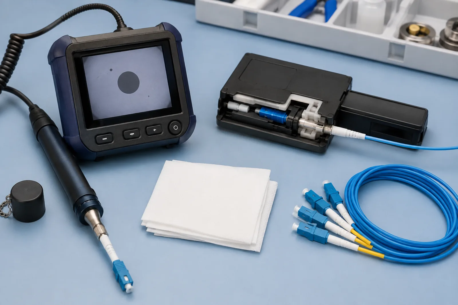
Summary: A reliable fiber connector inspect clean inspect procedure has a closed loop: inspect both mating end faces, clean only with approved materials when needed, reinspect, and connect only after acceptance. Record repeat failures and protect test leads and equipment ports from cross-contamination.
This workflow covers field handling and incoming inspection. It does not claim that a clean-looking connector automatically meets insertion-loss or reflectance requirements.
Why inspection comes first
Dust, oil and residue can obstruct the fiber core region, increase loss or reflection, and transfer to the opposite side when connectors mate. A protective cap reduces exposure but is not cleanliness evidence.
FOA Standard FOA-8 instructs users to inspect, determine whether cleaning is needed, clean with purpose-made methods and inspect again. VIAVI’s fiber guide presents the same inspect–clean–reinspect–connect loop and emphasizes inspecting both sides of a connection.
Inspection also distinguishes removable contamination from permanent damage. Repeatedly scrubbing a scratched or chipped end face is not a repair method and can waste consumables or harm the interface.
Make the interface safe to inspect
Identify the circuit and follow the site’s optical safety and service procedure. Do not look into a fiber with an ordinary microscope when optical power may be present. A video inspection probe keeps the user’s eye away from the optical path and is preferred where required by procedure.
Use the correct tip for the connector or bulkhead. A poorly fitting adapter can prevent focus, damage the ferrule or miss part of a multifiber end face. Keep inspection-probe tips clean because a contaminated tool can compromise repeated checks.
Inspect both mating sides
Disconnect according to the approved service plan. Inspect the patch-cord connector, then the connector inside the adapter, transceiver or equipment port using the correct probe. Do not assume the inaccessible side is clean because the exposed side passes.
Record connector ID, location, polish, inspection tool, operator, time and initial result. If automated analysis is used, record the selected acceptance profile and preserve the image. A green icon without the profile or image is weak evidence.
Use a controlled cleaning decision
Prepare a clean work surface and separate used consumables from fresh ones. Close containers promptly and replace caps on unused interfaces. A cleaning stick or wipe is not clean merely because it looks unused; follow its single-use or advancement instructions and protect it from the bench surface.
For multifiber connectors, use tools and inspection criteria intended for the full ferrule geometry. Guide pins, holes and the large contact area can retain debris outside the immediate fiber zones and later move it during mating. Do not apply a single-fiber tip or acceptance image to an MPO interface.
| Initial observation | Controlled action | Required follow-up |
|---|---|---|
| Clean and undamaged | Do not clean unnecessarily | Connect promptly and protect unused ports |
| Loose dry contamination | Use approved dry method | Reinspect both mating sides |
| Oily film or persistent residue | Use approved wet-to-dry method | Allow proper drying and reinspect |
| Scratch, pit or chip remains | Stop repeated cleaning | Quarantine or evaluate per acceptance plan |
| Contamination repeatedly returns | Investigate adapter, cap, tool and work area | Correct source before further mating |
FOA’s connector-cleaning guidance describes lint-free wet/dry cleaning and warns that unsuitable materials can leave fibers or residue. Use only products approved by the equipment and connector suppliers. Check chemical safety requirements, especially near fusion-splicing arcs or in confined environments.
Dry cleaning
A cassette or purpose-made probe can be convenient for light contamination. Advance to a fresh cleaning surface as directed. Do not reuse a dirty section or press with uncontrolled force. Static and redeposition remain possible, so the post-clean inspection is mandatory.
Wet-to-dry cleaning
When an approved fluid is required, use a clean lint-free surface and move from damp to dry according to the product method. Do not flood the connector or mate it while fluid remains. Household tissues, clothing and unapproved swabs can shed material or introduce oils.
Reinspect before connecting
Return the end face to the inspection tool without touching it. Use the same acceptance profile and store the after image when documentation is required. If contamination remains, repeat with a suitable controlled method rather than declaring success based on the cleaning action alone.
Set an escalation rule. For example, after two documented cleaning attempts, pause and inspect the cleaning tool, adapter and opposite interface. This is an operational rule, not a universal standard, but it prevents endless cleaning from concealing physical damage.
Protect reference cords and test ports
Reference test cords can undergo many matings and can spread contamination across an entire acceptance batch. Inspect their ends before setting a zero reference and after any suspect mating. If a reference cord is disconnected after referencing, follow the test method’s rules for re-establishing the reference.
Equipment output and input ports also need controlled inspection and cleaning. A dirty source port can change launched power; a dirty meter adapter can affect repeatability. Include these interfaces in the test-kit maintenance log.
Separate visual and optical acceptance
Define the applicable inspection criteria in the work order. Different connector geometries and applications can use different zones, scratch limits and defect rules. The operator should not select a more permissive profile after seeing a failure. Any deviation requires a documented technical decision.
Optical retesting after cleaning should preserve the original reference condition or establish a new one according to the method. A lower loss after reconnecting may result from cleanliness, mating repeatability or reference changes. Record enough detail to distinguish these effects rather than crediting the cleaning tool automatically.
A connector can pass visual cleanliness inspection yet fail a project loss or reflectance limit due to alignment, polish geometry, damage outside the visual rule or another component. Conversely, a visible defect may require interpretation under the governing standard and optical performance plan.
Therefore keep two fields in the record: end-face inspection result and optical test result. Do not convert one into the other. Our low-loss patch-cord acceptance guide explains the separate optical checks; multifiber assemblies also require the correct geometry-specific inspection profile.
Specify cleanable, inspectable assemblies
The commercial fiber optic patch cord page is the appropriate destination for connector type, polish, fiber type, length and test-document requests. State whether individual end-face images or optical results are required; do not assume a dust cap is a certificate.
For field kits, the fiber optic tools page helps frame inspection-probe tips, cleaning consumables and test accessories. Match tools to LC, SC, MPO or recessed bulkhead interfaces actually present.
Close the loop with traceable records
For incoming inspection, select samples using the purchase plan and keep product lot and packaging information. If contamination is widespread, stop opening more units until handling and packaging are reviewed. Cleaning every received connector can conceal a recurring supplier or storage-control problem.
For live operations, coordinate service impact and avoid unnecessary unmating. A clean, stable connection does not benefit from routine disconnection solely for inspection. Apply the process whenever an interface is opened, newly installed, under test or implicated in a fault, subject to the site’s maintenance policy.
A concise log includes before image, method, consumable lot if required, after image, acceptance profile, connector identity and optical result. For a failed end face, record quarantine or replacement rather than deleting the first image.
The habit is deliberately repetitive: inspect, clean if necessary, reinspect, then connect. It reduces cross-contamination and makes troubleshooting evidence reproducible without pretending that visual appearance alone certifies the finished link.
Frequently Asked Questions
Should a new patch cord be inspected before first use?
Yes. Protective caps reduce exposure but do not prove the end face is clean. Inspect both mating sides before connection under the approved procedure.
Can I clean a connector without inspecting it first?
Cleaning may be necessary when inspection is unavailable under an emergency procedure, but it gives no evidence of contamination type or final condition. The preferred controlled workflow begins and ends with inspection.
Should both sides of an adapter connection be checked?
Yes. A clean patch-cord plug can be contaminated by a dirty bulkhead-side connector, and contamination can transfer when the pair is mated.
Can a microscope prove optical performance?
No. Inspection evaluates visible end-face condition against the selected criteria. Project-required insertion-loss or reflectance testing remains a separate measurement.
Is canned air a universal fiber cleaning method?
No. Some products can introduce propellant or residue. Use cleaning products and methods approved for the connector, equipment and work environment.







