
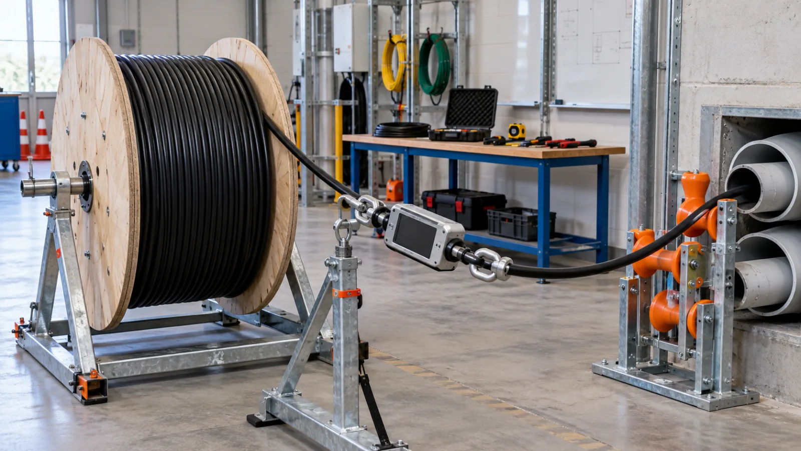
Summary: A defensible fiber optic cable pulling tension calculation follows the cable through every straight section and bend, compares the highest tension with the cable manufacturer’s maximum pulling tension, and checks bend sidewall pressure separately. The worked figures below are planning examples, not Liqiba test data.
Use the cable manufacturer’s current installation sheet as the controlling source. Route geometry, lubricant, conduit condition, pulling eye, temperature and equipment all affect the result. A calculation cannot make a damaged or obstructed pathway safe.
Start with the two different mechanical limits
Maximum pulling tension protects the cable from excessive axial load. Sidewall pressure describes the radial load where a tensioned cable bears on a bend. A route can pass the tension limit yet fail the bend-pressure limit, so both checks belong in the plan. Bend radius is a third independent requirement.
CommScope’s fiber construction manual instructs installers to observe maximum pulling tension, use the correct pulling grip and monitor load with a dynamometer. It also describes breakaway swivels as protection against exceeding the rated tension.
Calculate the route in the direction of pull
Divide the pathway into straight sections and bends, starting where the cable enters. For a simplified straight conduit section, an estimator may use added tension equal to cable weight per unit length multiplied by length and an assumed friction factor. Real design software may account for slope, fill, existing cables and more detailed friction models.
For a bend, tension increases because of friction around the arc. A common capstan model is T-out = T-in × e^(μθ), where μ is an assumed friction coefficient and θ is bend angle in radians. The model is sensitive to μ: document whether it comes from a validated lubricant/cable combination or is merely a conservative planning assumption.
Check sidewall pressure at every bend
A simple single-cable planning relationship is sidewall pressure = bend-exit tension ÷ bend radius. Keep units consistent: newtons divided by metres gives newtons per metre. The governing manufacturer may prescribe a different method or unit convention.
CommScope’s conduit construction manual illustrates the T/R relationship for bend pressure and emphasizes calculating the complete run. Its product context is not a substitute for the selected fiber cable’s data sheet.
Control the pull in the field
Inspect and rod the pathway, verify ducts and handholes, clean the route and set rollers so the cable never rides a sharp edge. Use an approved pulling eye or grip that transfers load into the strength members as instructed. A swivel helps prevent torsion; it does not raise the cable rating.
Place the calibrated tension monitor where the crew can act on it. Establish a stop value below the maximum to account for response time and uncertainty. Stop for a sudden rise, snag, displaced roller or loss of communication; do not use extra pulling force to diagnose an obstruction.
Our fiber cable bend-radius guide explains installed and pulling-radius checks, while the tensile and crush test guide separates laboratory qualification from field handling.
Worked pulling worksheet
Assume a hypothetical cable weighing 0.20 kg/m, a 60 m level conduit, friction coefficient 0.25, then a 90-degree bend of 1.0 m radius. Use weight force 0.20 × 9.81 = 1.962 N/m.
| Step | Formula | Result |
| Straight section | 1.962 × 60 × 0.25 | 29.4 N |
| 90° bend | 29.4 × e^(0.25 × 1.571) | 43.6 N |
| Sidewall pressure | 43.6 ÷ 1.0 | 43.6 N/m |
| Decision | Compare independently | Use exact cable limits |
These low illustrative values omit feed tension, slope, multiple cables and pathway irregularities. Add all route sections in sequence and compare the peak values with the exact cable and hardware limits.
Turn the method into a procurement specification
A useful request for quotation identifies the application, fiber type, connector or cable construction, operating wavelengths, environmental range, installation method and the evidence required at delivery. It separates mandatory acceptance limits from preferences. Asking only for “high quality” leaves supplier and buyer with different interpretations; a measurable requirement gives both parties the same decision point.
Record units, reference conditions and rounding rules. State whether a value is maximum, typical or informational, and whether it applies to every unit, a sample or a type test. Where a standard defines a method but the project chooses the limit, cite both separately. The project owner should resolve conflicts among the drawing, purchase order, product data sheet and field procedure before work starts.
For relevant products, use the commercial fiber optic cable supplier page. Send the route, interface or test details with the inquiry so the proposed construction can be checked against the actual application rather than selected by a generic label.
Build an auditable acceptance record
The record should connect the asset identifier to the instrument, settings, operator, date, reference method and result. Preserve native test files when the instrument creates them; a screenshot alone can hide settings or event detail. Photographing labels and end positions can reduce later ambiguity, but photographs do not replace optical or mechanical evidence.
Use a defined disposition for a result near or beyond the limit: verify identification, inspect the setup, repeat only under the written repeatability rule, and then accept, rework or escalate. Do not keep testing until one favorable reading appears. If uncertainty is material, use a guard band or engineering review established before testing.
After installation, keep the approved design value, as-built value and any deviation together. That baseline supports troubleshooting after moves, adds or environmental changes. It also prevents a later team from treating a planning calculation as factory data or a field observation as a universal product specification.
Common mistakes to prevent
Do not pull by the jacket when the construction requires a strength-member attachment, and do not attach to connectors unless the assembly is specifically designed for that method. Avoid uncontrolled vehicle pulls, unverified lubricants, tight figure-eight stacks, reverse bending and cable twist.
Another frequent error is copying a number from a different cable, splitter, connector or instrument. Manufacturer limits depend on construction and test conditions. Confirm the exact data sheet and revision. When a worked value in this article is used, retain its assumptions and replace them with project values before making a purchase or acceptance decision.
Finally, keep safety and handling instructions in the work package. Optical fibers create sharp fragments; live systems may carry invisible radiation; pulling and test equipment can store mechanical energy. Qualified personnel should follow the site procedure, product instructions and applicable regulations.
Use a pre-work review and hold point
Before installation or testing begins, review the latest drawing, bill of materials, product revision and acceptance procedure with the people who will perform the work. Confirm which document controls if values disagree. Assign a unique identifier to the link or component and place that identifier on the worksheet, instrument file and any photograph. This prevents a technically correct result from being attached to the wrong asset.
Create a hold point before concealed work is closed or an irreversible change is made. Check the physical routing, labels, connector condition, test reference and recorded settings. If the result is abnormal, pause while the relevant section remains accessible. The hold point should identify who can release the work and what evidence is required.
Evaluate changes after delivery
Transport, storage and installation can change condition after a supplier’s outgoing inspection. Define which checks occur at receipt, before installation and after completion. Keep packaging damage, seal condition and storage observations with the receiving record. Do not treat a factory certificate as proof that later field handling caused no change.
When a repair, reroute or replacement occurs, update both the technical record and configuration drawing. Reuse the same measurement method where practical so results remain comparable. If a new instrument or procedure is necessary, document the difference instead of presenting unlike measurements as a continuous trend. A clear change history makes future fault isolation faster and supports fair supplier discussions.
Archive superseded worksheets without deleting them, mark the approved revision clearly, and give field teams read access to the version that governs their work.
Frequently Asked Questions
Is maximum pulling tension the same as tensile strength?
No. Use the manufacturer’s installation maximum for the exact cable; laboratory qualification or ultimate strength is not a field working limit.
Why check sidewall pressure if tension is below the maximum?
A small-radius bend concentrates radial load. The cable may pass the axial limit while exceeding the permitted pressure at that bend.
Can the friction coefficient be assumed as 0.25?
Only as a clearly labeled planning assumption. Use validated project or manufacturer data for the actual cable, duct and lubricant.
Where should tension be measured?
At a location and with equipment defined by the pull plan, normally so peak pulling load can be observed and a stop command issued immediately.
Does lubricant always permit a longer pull?
No. It must be compatible with cable and conduit, correctly applied, and supported by the design assumptions. It cannot correct an obstructed pathway.







