
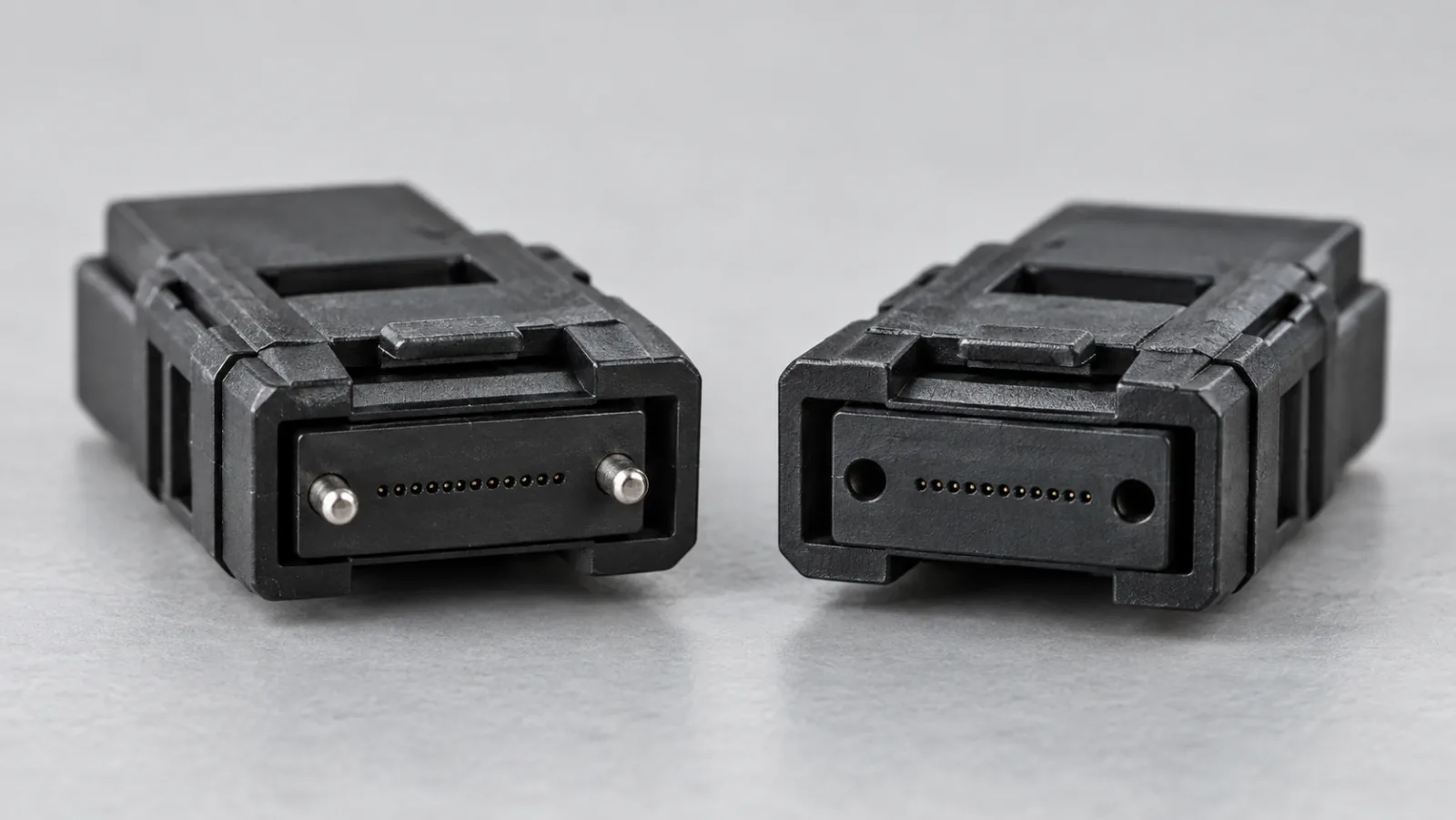
Summary: An MPO male vs female connector compatibility check starts with one pinned ferrule mating to one unpinned ferrule. That mechanical rule is necessary, but a usable connection also requires compatible connector geometry, fiber arrangement, polish and polarity. Record each interface in the channel before ordering trunks or equipment cords.
This guide focuses on pin configuration and procurement checks. It does not assign one universal cord design to every transceiver. The example channel is a hypothetical planning exercise, and all equipment-side details must be checked against the actual module documentation.
Identify pins on the ferrule, not the cable label
A male MPO connector has alignment pins; a female MPO connector has receiving holes without those pins. The pins align the mating ferrules. A connector housing that latches into an adapter does not establish that the optical interfaces are correctly matched.
Fluke Networks’ MPO connectivity guide explains the pinned and unpinned distinction and notes that active equipment commonly uses pinned interfaces. Treat that as a common arrangement to verify, rather than an excuse to skip the exact equipment drawing.
Use an appropriate inspection system and the manufacturer’s handling instructions. Do not attempt to prove compatibility by forcing two connectors together. Pin-to-pin contact can damage the interface; an unpinned-to-unpinned combination lacks the intended alignment mechanism even if the outer housings appear to fit.
Keep gender, polarity and adapter orientation separate
Gender describes the pins. Polarity describes where each fiber position leads. Adapter key orientation controls how the housings face each other. These properties interact in an installed channel, but changing one does not automatically correct the others.
A correctly pinned connection can still deliver a transmitter to the wrong receiver. Conversely, a drawing with correct fiber mapping can specify mechanically incompatible ferrules. Maintain separate columns for pin state, key arrangement and position-to-position mapping in the bill of materials.
The MPO polarity Types A, B and C guide covers fiber mapping. Use it alongside this interface check, then validate the full end-to-end lane map. Do not rewrite a proven polarity design simply because a replacement jumper’s pin state differs.
Check more than the nominal fiber count
An order that says only “MPO, twelve fibers” leaves several decisions unresolved. Confirm single-mode or multimode fiber, ferrule family, populated positions, end-face polish, key arrangement, loss grade and both ends’ pin states. For higher-count interfaces, confirm row layout and the manufacturer’s intermateability requirements.
Do not assume an MPO-16 interface accepts an MPO-12 assembly because both names contain MPO. A different key location or ferrule layout can intentionally prevent incompatible mating. Similarly, a connector with fewer active fibers may use a familiar housing while requiring a specific lane arrangement.
US Conec’s connector FAQ explains that alignment depends on the ferrule and guide-pin geometry and identifies the relevant MPO interface standards. It also distinguishes its MTP connector implementation from the generic MPO interface. A brand term alone does not describe the full assembly configuration.
Create a connection-by-connection compatibility matrix
Assume a hypothetical two-panel channel. Both equipment ports are confirmed pinned. The trunk is pinned at both ends, and each equipment cord is unpinned at both ends. The panels use compatible adapter housings rather than introducing another ferrule. This produces the following mechanical pairings.
| Junction | First ferrule | Second ferrule | Mechanical result |
|---|---|---|---|
| Equipment A to cord A | Pinned equipment | Unpinned cord | Complementary |
| Cord A to trunk | Unpinned cord | Pinned trunk | Complementary |
| Trunk to cord B | Pinned trunk | Unpinned cord | Complementary |
| Cord B to equipment B | Unpinned cord | Pinned equipment | Complementary |
This table establishes only pin compatibility under the stated assumptions. It says nothing about whether the polarity works, whether the link meets its optical loss budget or whether the equipment supports the selected fiber type. Those checks remain independent release conditions.
Test the effect of one replacement
If a replacement trunk arrives unpinned at both ends, its junctions with the existing unpinned equipment cords become unpinned-to-unpinned. The equipment junctions still appear correct, so a quick check at the switches can miss the problem. Reviewing all four rows catches the mismatch before installation.
Resolve the mismatch by selecting the approved assembly configuration or following a manufacturer-authorized conversion procedure. Do not add miscellaneous adapters as an improvised fix. A conventional adapter aligns the housings; it is not a substitute for the required guide pins at the ferrule interface.
Control field-changeable connectors
Some connector systems allow documented field changes to pin configuration or polarity. Confirm that the exact connector supports the operation, obtain the specified tool and follow the manufacturer’s procedure. Never infer serviceability from another product in the same family.
After a permitted conversion, update the assembly label and record its new configuration. Inspect the ferrule, guide holes and pins, then repeat the required continuity and optical tests. A successful mechanical conversion does not prove cleanliness or lane mapping.
For spares, keep a controlled stock list by both end configurations. Separate convertible assemblies that have already been altered from factory configuration. Otherwise a technician may select a nominally identical part whose last field change was never recorded.
Prepare inspection and test accessories for both ends
An inspection tip must suit the connector and provide a useful view of the fiber array. Verify that the cleaning tool is compatible with pinned or unpinned ferrules as required. Contamination near the alignment features can affect mating even when the fiber region looks clean.
The MPO end-face inspection guide addresses inspection criteria. Keep its optical cleanliness decision separate from the gender checklist: a clean connector may still be the wrong mechanical part, and a correct part may still require cleaning.
Reference cords used for insertion-loss testing must also have complementary interfaces and the required performance grade. Confirm the test reference method before selecting accessories. Do not improvise a long chain of adapters to make the test instrument connect, because that can change the reference boundaries and uncertainty.
Keep cassette boundaries visible in the drawing
A cassette introduces interfaces that may be hidden behind the panel. Record the rear connector’s actual ferrule configuration, not just the front LC presentation. For a replacement cassette, compare the rear gender, fiber mapping and interface specification with the original approved model before accepting it as equivalent.
Label the near and far views on drawings. Looking into a connector face and looking from the cable side can reverse the apparent position order. A photograph can support pin identification, but a controlled end-view drawing is more reliable for communicating lane mapping across purchasing, installation and testing teams.
For a phased upgrade, retain separate matrices for the current channel and the intended final channel. A temporary jumper may be valid for one stage but unsuitable for the completed layout. Include the replacement step in the work order and remove obsolete temporary labels when the final test is accepted. This prevents a future repair from restoring an intermediate configuration by mistake.
Write a purchase description that survives substitution
For the MPO/MTP patch cord product page, supply the exact equipment interfaces, fiber type, length, populated positions, end A and end B pin states, polish and approved polarity map. Attach a simple channel drawing with the mating counterpart named at every endpoint.
Specify how substitutions will be reviewed. A supplier should identify a changed ferrule family, connector model, boot geometry or pin configuration before shipment. Mechanical fit at one isolated interface is insufficient evidence for the complete installed channel.
At receipt, compare assembly labels with the approved matrix and inspect representative interfaces under the quality plan. Preserve per-fiber test records where requested. When the system is installed, label the completed channel so future maintenance can reproduce the same configuration without reopening the original design decisions.
A short, accurate interface schedule is usually more useful than ordering every jumper as “standard MPO.” It makes pin compatibility explicit, keeps polarity checks visible and allows spares to be selected against the actual connection rather than a remembered convention.
Frequently Asked Questions
What makes an MPO connector male or female?
Male means the ferrule has alignment pins; female means it has guide holes without the pins.
Can two female MPO connectors be joined through an adapter?
That arrangement lacks the intended pinned-to-unpinned ferrule alignment. A conventional housing adapter does not supply the missing guide pins.
Does correct MPO gender guarantee correct polarity?
No. Pin compatibility and fiber position mapping are separate checks. Both must match the channel design.
Can MPO connector gender be changed in the field?
Only when the exact connector supports a manufacturer-authorized procedure. Record the change and repeat required inspection and testing.
Should every equipment cord have unpinned connectors?
Equipment interfaces commonly use pins, but verify the actual interface and each mating junction before specifying the cord ends.







