
Summary: A 144 fiber cable color code chart becomes reliable only when it is tied to the cable’s actual construction. For the common arrangement of twelve numbered tubes containing twelve fibers each, the global fiber number is twelve times the preceding tube count plus the local fiber position. Use the manufacturer’s color schedule and verify circuit identity before splicing.
The worksheet below assumes twelve fully populated tubes, numbered from one, with the same twelve-color sequence for tubes and fibers. It does not cover every 144-fiber ribbon, central-tube or custom-coded design. The examples are numbering calculations, not an as-built record of a Liqiba project.
Confirm the construction before applying a color chart
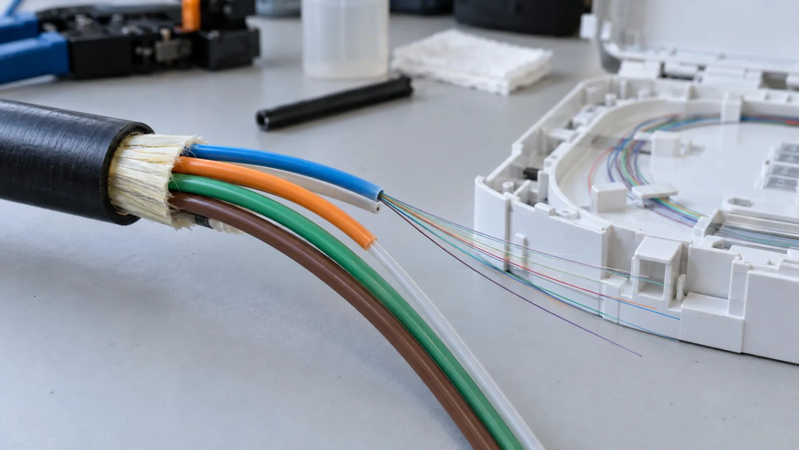
The total fiber count does not uniquely describe the internal organization. A 144-fiber cable might use twelve tubes of twelve fibers, a different tube population, ribbons or other identifiable subunits. Fillers can resemble tubes but contain no optical fibers. Read the construction drawing before assigning tube numbers.
The Fiber Optic Association’s color-code reference explains the common TIA-based sequence and notes that national practices and customer requirements can differ. Color is a useful identification system, but it is not universal proof of position or fiber type.
Ask for the exact production color schedule with the cable data sheet. Confirm whether a stripe, binder, ring or printed ribbon number distinguishes repeated color groups. Retain a legible copy with the splice plan so a field team does not depend on a generic chart downloaded from memory.
Keep tube position and fiber position separate
In the assumed twelve-by-twelve arrangement, each tube has a local fiber sequence starting at one. The first blue fiber is globally number one only when it is inside the first tube. A blue fiber inside the second tube is number thirteen; inside the final tube it is number 133.
FOA’s outside-plant cable guide describes the common twelve-fiber-per-tube arrangement and repeated color sequence up to 144 fibers. The table below combines that convention with calculated global ranges for this specific construction.
| Tube position | Tube color | Global fiber range | Local fiber color at the same position |
|---|---|---|---|
| 1 | Blue | 1–12 | Blue |
| 2 | Orange | 13–24 | Orange |
| 3 | Green | 25–36 | Green |
| 4 | Brown | 37–48 | Brown |
| 5 | Slate | 49–60 | Slate |
| 6 | White | 61–72 | White |
| 7 | Red | 73–84 | Red |
| 8 | Black | 85–96 | Black |
| 9 | Yellow | 97–108 | Yellow |
| 10 | Violet | 109–120 | Violet |
| 11 | Rose | 121–132 | Rose |
| 12 | Aqua | 133–144 | Aqua |
The last column defines positions one through twelve inside every tube. It does not say that every fiber inside the blue tube is blue. For example, the red fiber in the blue tube is global fiber seven under this schedule.
Calculate the global number in both directions
Let T be the tube number and F the local fiber number, both starting at one. The global number N is N = 12 × (T − 1) + F. Check that T and F each lie between one and twelve before calculating.
Example: locate the black fiber in the red tube
Red is tube seven and black is local fiber eight. Therefore N = 12 × 6 + 8 = 80. Write the record as “cable C1, tube 7 red, fiber 8 black, global 80.” Recording all four identifiers makes the calculation independently checkable.
Example: identify global fiber 101
The inverse calculation is T = floor((N − 1) ÷ 12) + 1, followed by F = ((N − 1) modulo 12) + 1. For N = 101, T is nine and F is five. That gives the slate fiber in the yellow tube.
Boundary values are useful spreadsheet checks. Fiber twelve must remain in tube one, fiber thirteen begins tube two, and fiber 144 is the final fiber of tube twelve. An off-by-one error usually appears immediately at those boundaries. Preserve these test cases when copying a worksheet.
Map unlike cables with a cross-connect schedule
When two cables use the same construction and coding, matching colors can support a straight continuation. When constructions differ, the splice schedule must define the intended global circuit mapping. Do not assume a twelve-fiber branch should connect to a same-colored tube in a larger feeder.
As a hypothetical branch plan, feeder fibers 73–84 might be assigned to branch fibers 1–12. Under the assumed convention, the feeder group lies in its red tube, while the branch may have a single tube with a different identifier. The mapping is valid because of the approved circuit plan, not because outer colors match.
Use one row per splice with incoming cable ID, tube, fiber, global number, outgoing cable ID and corresponding positions. Add tray and sleeve positions as separate fields. The splice tray capacity guide supports physical placement, while the fusion splice acceptance guide addresses optical evidence after joining.
Verify identity before cutting or splicing
First reconcile cable markings at the closure with the route drawing. Then identify the tube or ribbon, and finally the individual fiber. Keep unworked groups secured and separated so movement during preparation does not mix adjacent fibers. Good lighting and a neutral background help distinguish similar shades.
When color is uncertain, stop and use an approved identification or continuity procedure. A visible-light source may help on suitable isolated paths, but it does not establish that a production circuit is safe to interrupt. Follow the operator’s authorization and live-fiber procedures.
Two-person readback is useful for a critical splice: one person names the incoming and outgoing positions, and another compares them with the approved row. Optical testing after the splice cannot by itself prove that a low-loss joint connects the correct customer’s circuit.
Account for ribbons, binders and partially filled units
If the cable uses ribbons, record ribbon identity and fiber order using the manufacturer’s viewing convention. Turning a ribbon over can reverse the apparent order. Never transfer a loose-tube formula to a ribbon stack without defining how ribbon numbers correspond to global numbers.
For partially populated tubes, global numbering may skip reserved positions or continue through only installed fibers, depending on the design. A generic twelve-position formula can then be wrong even though the colors look familiar. Obtain the actual fiber allocation drawing and use its rules consistently.
Photograph representative identification features during receiving inspection and store the approved legend with the reel record. Photographs assist recognition; the controlled written schedule remains essential when lighting, dirt or faded markings make colors difficult to distinguish.
Validate the worksheet before using it in a closure
A numbering spreadsheet should reject inputs outside its supported construction. For this example, tube zero, local fiber thirteen and global fiber 145 are errors. Blank cells should remain unassigned rather than becoming zero through a formula. Add a visible construction field so the sheet cannot be mistaken for a universal cable calculator.
Check uniqueness within each cable: two rows should not allocate the same fiber to different circuits unless the design deliberately records the same continuous circuit at different locations. Check both directions of every planned splice. Incoming fiber 80 mapped to outgoing fiber eight must produce the same pair when the outgoing schedule is read back.
Finally, compare the number of allocated, spare and reserved fibers with the actual installed count. A spare fiber is still a physical position and should retain its identity. Keeping spare assignments visible helps future expansion use the intended capacity without accidentally consuming a fiber reserved for restoration or another branch.
Include identification requirements in the cable order
When using the fiber optic cable supplier page, specify total fibers, fibers per tube or ribbon, color convention, repeated-group markings, spare or filler units and required production drawings. Request a sample identification schedule before approving a custom construction.
At handover, retain the cable schedule, splice map, tray locations and test file names under the same route identifiers. If a repair changes the allocation, update both ends of the record. The practical goal is that another technician can locate the intended fiber, reproduce the numbering calculation and verify the circuit without relying on the original installer’s memory.
Frequently Asked Questions
Does every 144-fiber cable contain twelve tubes of twelve fibers?
No. Tube populations, ribbons and subunit arrangements vary. Confirm the construction drawing before using this worksheet.
How do I calculate the global fiber number?
For the stated twelve-by-twelve construction, use N = 12 × (tube number − 1) + local fiber number, with numbering starting at one.
Which fiber is number 101 in this example?
It is local fiber five, slate, in tube nine, yellow, under the stated color convention.
Should identical colors always be spliced together?
Only when the approved circuit mapping calls for it. Branch cables and different constructions may require different global number assignments.
Can cable jacket color identify a specific internal fiber?
No. Internal identification requires the cable ID, tube or ribbon identifier and the local fiber position.







