
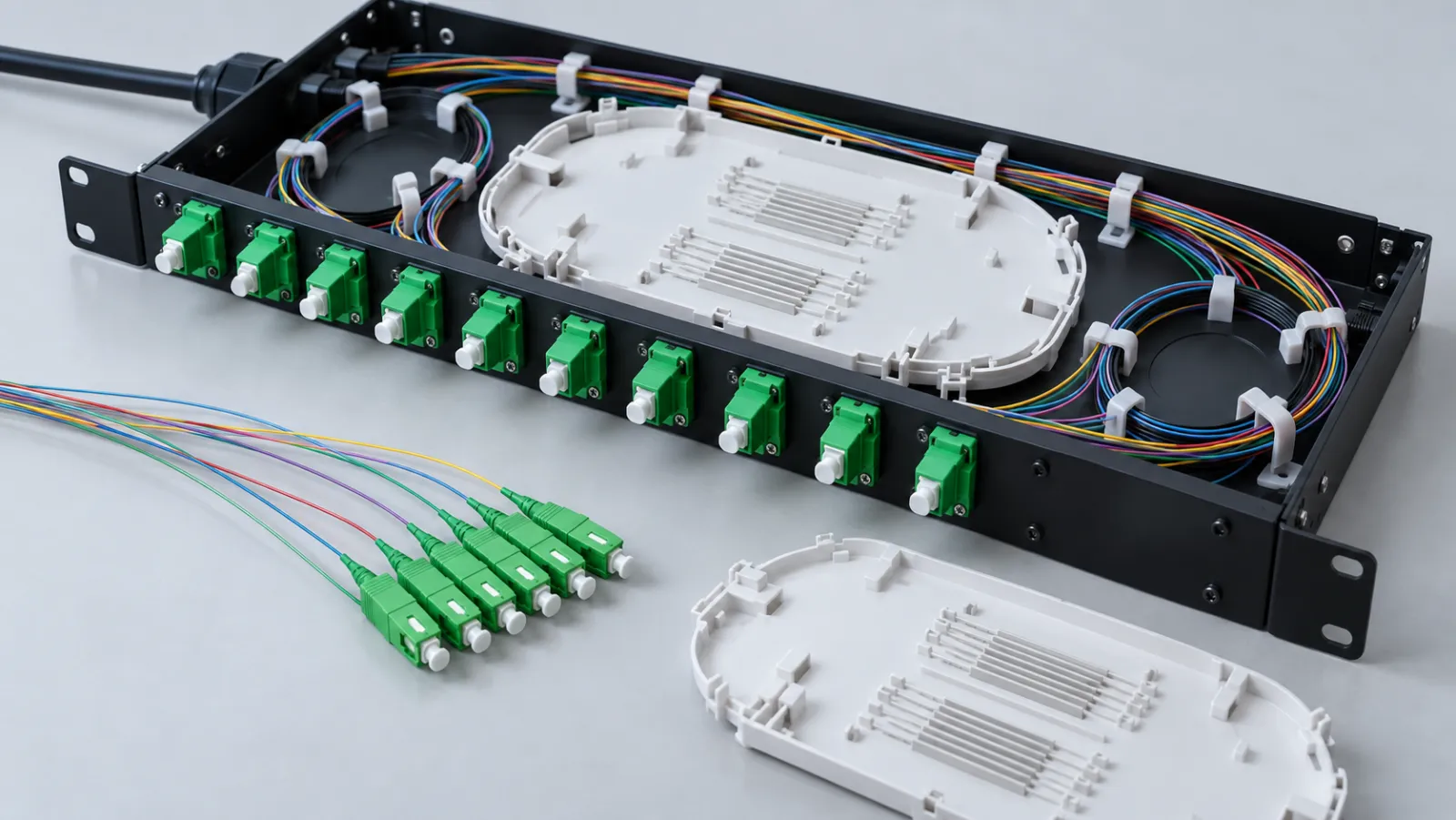
Summary: Choosing 250 vs 900 micron fiber pigtails is primarily a mechanical routing and termination decision, not a choice between two optical core sizes. Confirm what the quoted diameter describes, how the fiber is protected between the connector and splice, and whether the panel, tray, holders and preparation tools support that construction. Specify optical fiber type and connector performance separately.
A pigtail has a connector at one end and a fiber tail intended for a defined termination method at the other. This guide focuses on fusion-spliced panel installations. All dimensions and procurement quantities in the worked examples are illustrative, not specifications for an identified Liqiba product.
Separate glass, coating and secondary buffer
A conventional communications fiber may have 125 µm glass cladding with a protective polymer coating around it. A nominal 250 µm coated fiber and a nominal 900 µm buffered fiber therefore describe different protective layers around the optical fiber. Neither number alone states the core diameter, single-mode performance category or connector polish.
Extron’s fiber cable construction reference illustrates the relationship between glass, coating, secondary buffer and outer jacket. It also distinguishes a protective fan-out tube from the more complete protection of a jacketed breakout arrangement. That distinction matters when a quotation uses the word “buffered” without a construction drawing.
Ask whether the 900 µm element is tight-buffered, semi-tight or a tube surrounding a smaller coated fiber. Confirm the actual nominal sizes and tolerances with the supplier. Other coating sizes exist, so “250” should not be assumed for every modern high-density fiber construction.
Use protection needs to define the routing
A fine coated tail can be appropriate inside a compatible protected routing system. It should not be treated as a general-purpose equipment jumper simply because its connector can mate with an adapter. Identify where the tail leaves the connector, enters a routing channel and reaches the splice tray.
A 900 µm buffer can provide additional handling protection, but it does not automatically supply the strength members, jacket or strain relief of a complete patch cord. The panel still needs to prevent unsupported movement and local stress. Check the whole assembly rather than ranking the larger diameter as universally better.
AFL’s panel pigtail description provides a manufacturer example of 900 µm tight-buffered assemblies with several connector interfaces. It demonstrates that buffer construction and connector choice are separate order fields; it does not establish availability, certification or performance for a different supplier’s assembly.
Compare the complete installation interfaces
The useful comparison is not just diameter versus price. Record every point that will grip, guide or prepare the pigtail. A tray that accepts the final splice protector may still have an unsuitable entry channel for the buffered fiber, while an acceptable entry channel does not prove the connector boot fits behind the adapter.
| Selection question | Nominal 250 µm coated tail | Nominal 900 µm buffered tail |
|---|---|---|
| Protection along route | Needs compatible protected routing | Confirm buffer construction and enclosure support |
| Preparation | Tool must match the actual coating | May require a separate buffer-removal step |
| Tray entry | Check fine-fiber retention without damage | Check entry size and permitted stripping transition |
| Optical specification | Specify fiber category and connector independently | Specify the same independent optical requirements |
| Substitution review | Evaluate routing, handling and identification | Evaluate bulk, preparation and movement clearance |
This table is a design-review framework, not approval to interchange the constructions. Obtain the actual enclosure and assembly instructions before final selection. The site’s splice tray capacity guide provides the related check on sleeves and circuit allocation, which remains separate from buffer compatibility.
Estimate routing space without inventing a fill limit
For a simple geometric comparison, treat each nominal fiber element as a solid circular cross-section. Area is πd²/4. At 0.25 mm diameter the area is approximately 0.0491 mm²; at 0.90 mm it is approximately 0.6362 mm². The diameter ratio is 3.6, but the cross-sectional area ratio is 12.96.
For 24 elements, the summed nominal areas are about 1.18 mm² and 15.27 mm² respectively. This calculation explains why a seemingly small diameter change can materially affect a crowded internal route. It is not a permissible channel-fill percentage or a prediction that one tray holds thirteen times as many fibers.
Include the real restrictions before choosing a tray
Actual routing must account for packing gaps, crossings, curvature, retainers, manufacturing tolerances and access during maintenance. A routing slot may be constrained by its width or height rather than its area. The applicable bend requirement and the panel manufacturer’s approved fiber count remain controlling.
Use a physical layout review or representative mock-up where appropriate. Check the connector-to-tray path with the panel open, closed and in its intended service position. A configuration that fits only while the tray is fully extended may place tension on the pigtail when the drawer is closed.
Choose length from the actual internal route
Assume a hypothetical panel needs 0.55 m from the adapter to the tray entry, 0.70 m of approved stored routing length, and 0.20 m allocated for preparation and future rework. The preliminary total is 1.45 m. These allowances are chosen for this example and must not be treated as standard values.
A nominal 1.5 m pigtail appears to leave only 0.05 m beyond that total. Before ordering it, account for length tolerance, the specified measurement endpoints and variation between near and far adapter positions. A longer available assembly may be preferable only if the enclosure can store it without crowding or violating the bend requirement.
For a 48-port panel, create a length schedule by route group instead of assuming that every adapter has the same internal distance. Record which allowance is for normal routing and which is reserved for rework. This prevents future installers from consuming the maintenance reserve merely to reach the intended splice position.
Match stripping, holders and splice protection
Fusion splicing requires correctly prepared glass at the splice location. The external buffer diameter does not remain as the glass joint diameter. Confirm the permitted buffer-removal process, coating stripper, cleaver holder and splicer holder for the actual pigtail construction.
Do not prescribe a generic stripping length independent of the selected splicer, protector and tray. The transition from protected fiber to the splice region must follow their instructions. An easy-strip product and a tight-buffered product may require different handling even when their nominal outer diameters match.
After splicing, check that the chosen protector fits its holder and that routing into it is free from an abrupt bend. Keep the fusion splice acceptance guide separate from this mechanical review: a neat-looking sleeve does not establish the optical loss, and a good optical reading does not approve an unsupported routing arrangement.
Make the purchase description unambiguous
Specify fiber category, actual coating and buffer construction, connector type and polish, finished length and tolerance, color sequence, boot geometry, splice-end preparation and packaging. Include insertion-loss and return-loss requirements with their test method and sign convention. Avoid relying on “standard single-mode pigtail” as the complete description.
For a quotation through the custom fiber optic cable assembly page, attach the panel model or a controlled drawing of the connector-to-splice route. Ask the supplier to identify any proposed substitution before production, including a change from a tight buffer to a loose protective tube.
Define kit quantities carefully. For example, 48 installed positions plus four separately approved spares requires 52 individual pigtails. If the selected item is sold only in twelve-fiber kits, five kits provide 60 pieces, leaving eight beyond that planned requirement. Confirm whether colors, connector types and spare allocation make that packaging suitable before ordering.
Inspect the delivered construction before committing the panel
Compare labels, connector interfaces, colors and lengths with the approved schedule. Verify construction using supplier documents and the agreed incoming inspection method; avoid damaging working assemblies merely to confirm a dimension. Retain a controlled sample or photo record when the quality plan calls for one.
During a representative installation, check preparation behavior, routing clearance and the final closed-panel position. Record any mismatch before building the remaining ports. A replacement that changes buffer construction should repeat these checks even when the connector and fiber category are unchanged.
The best choice is the pigtail that matches the optical requirement and the complete mechanical path. A clear drawing, measured route allowance and construction-specific preparation plan are more useful than assuming that the smallest diameter always gives the best density or that the largest diameter always provides sufficient protection.
Frequently Asked Questions
Do 250 and 900 microns describe the optical core?
No. In this comparison they describe coated or buffered construction around the fiber. Specify the optical fiber category separately.
Is every 900 micron pigtail tight-buffered?
Do not assume so. Confirm whether the construction is tight-buffered, semi-tight or a protective tube around a smaller coated fiber.
Does a 900 micron buffer replace a patch-cord jacket?
Not automatically. A buffer alone does not establish the strength members, jacket or strain relief of a complete equipment patch cord.
Can geometric area determine a splice tray fiber count?
No. Nominal area illustrates bulk only; routing geometry, retention, bend requirements and the tray instructions determine usable capacity.
How should pigtail length be specified?
Measure the actual connector-to-splice route, add approved storage and preparation allowances, and define length endpoints and tolerance.







