
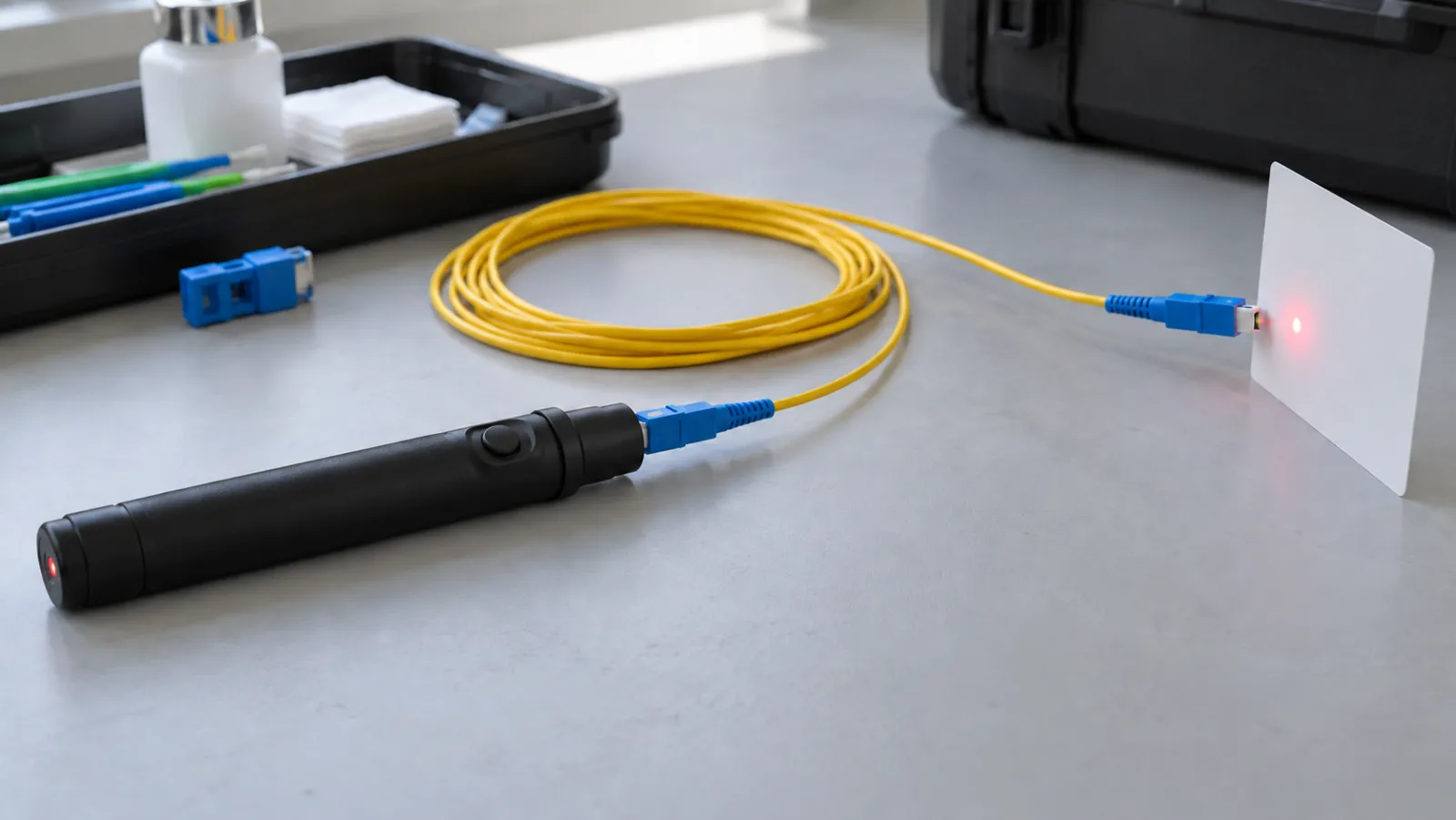
Summary: A visual fault locator fiber continuity test helps identify a fiber path and find some accessible faults, but it does not measure insertion loss or certify a communications link. Record which connector receives the visible signal, what route was tested and any abnormal light leakage. Then use the appropriate optical measurement method for the project’s acceptance decision.
This guide concerns authorized checks on disconnected fiber paths using a suitable visible-light instrument. It is not a live-network identification procedure. Follow the instrument’s laser-safety instructions and the network owner’s isolation requirements; never look into a fiber, connector or instrument port to decide whether it is active.
Define the question before choosing the tool
A continuity question asks whether light can follow the intended path between two identified endpoints. A polarity question asks whether the connections lead to the intended transmit and receive positions. A loss question asks how much optical power is lost under a defined measurement arrangement. Those are related but different tasks.
FOA’s visual tracing reference describes visible-light tools for identifying fibers, checking connections and locating some faults. A VFL can be particularly useful on short accessible assemblies. The presence of visible light at the destination does not establish acceptable loss at the service wavelength or prove that the entire cable is undamaged.
Write the intended result in the worksheet before testing. For example, “confirm panel A position 07 reaches panel B position 19” is a verifiable identification task. “Check that the cable is good” is too vague to distinguish successful tracing from installation acceptance.
Make the test boundary safe and unambiguous
Obtain authorization before disconnecting any service. Identify both ends from the controlled records and verify the required isolation using an approved method. A VFL cannot establish that an unknown network fiber is free of invisible optical power. Do not connect test equipment to a live service simply because no red light is visible.
Confirm that the locator, lead and adapter are appropriate for the connector and fiber arrangement. A mechanically convenient connection is not proof of compatible ferrule size or polish. Avoid forcing an adapter onto a connector or using improvised fittings that can contaminate or damage the interface.
Inspect and clean the interfaces using suitable equipment before mating. The inspect, clean and reinspect guide covers that separate preparation step. Check the VFL’s own connection interface as well as the installed fiber, because poor launch coupling can make a continuous path appear inconclusive.
Observe the signal without direct eye exposure
The instrument manufacturer’s viewing method controls. Fluke Networks’ VFL instructions describe observing the light from a connector on a white card. They also caution that light near the source can appear without a fault and that dark jackets can conceal visible leakage.
Use the approved target or detector arrangement rather than looking into the connector. Keep open ends controlled so they cannot point toward another person. Laser classification and output vary among instruments, so do not transfer one product’s safety classification to every pen-shaped locator on the market.
Where supported, steady and flashing modes can help distinguish the intended signal from background light. Record the chosen mode and coordinate with the person at the far end. Neither mode turns the observation into a calibrated optical power reading.
Trace one identified fiber at a time
Start with a uniquely identified source position. Ask the far-end technician to report the actual illuminated position before revealing the expected result where practical. This simple discipline reduces the risk of accepting the drawing by habit instead of recording what was observed.
Record both expected and observed destinations, including panel, adapter and fiber-side identifiers. Duplex housings need an agreed left/right or position convention viewed from a defined side. “The blue connector” is not a durable identifier in a panel containing many blue connectors.
| Source | Expected destination | Observed destination | Disposition |
|---|---|---|---|
| A-01, fiber 1 | B-01, fiber 1 | B-01, fiber 1 | Mapping confirmed for this path |
| A-01, fiber 2 | B-01, fiber 2 | B-02, fiber 2 | Investigate mapping discrepancy |
| A-02, fiber 1 | B-02, fiber 1 | No clear observation | Inconclusive; check setup and route |
These rows are invented teaching examples, not site test results. The third row is deliberately not labelled “broken fiber.” Lack of a visible result can reflect the instrument range, coupling, route loss, observation conditions or a genuine discontinuity.
Budget the identification workload
Assume a small installation has 24 individual fibers requiring one source-to-destination mapping check each. If preparation, coordinated observation and recording take an assumed 75 seconds per fiber, the basic workload is 1,800 seconds, or 30 minutes. Travel, isolation and corrective work are excluded.
Add exceptions without hiding them
If six fibers need a separate two-minute investigation, add twelve minutes. The illustrative total becomes 42 minutes before retesting corrected connections. If the approved method requires a reverse-direction check for every fiber, count that as another set of tasks rather than silently treating it as included.
A multi-fiber connector requires a supported way to identify its individual positions. Do not multiply a single-fiber timing estimate across an MPO assembly without accounting for the fan-out, mapping fixture and handling method. Record which physical positions were actually checked, not simply that the connector housing was tested.
Interpret visible leakage carefully
Red light escaping near an accessible bend or connector can identify a useful inspection location. It is an observation, not a quantified loss value. Stop and inspect the arrangement rather than making the bend tighter to obtain a brighter signal.
A localized glow should be recorded with its physical position, cable identity and the configuration at the time. If a lead is moved or a connector is reseated, note that intervention before repeating the observation. Otherwise a changed result may be attributed incorrectly to the original condition.
No visible leakage does not mean there are no faults. Opaque jackets, inaccessible routes and the characteristics of the signal can prevent an external observation. Avoid claiming a precise fault location inside a concealed route from the brightness seen at an endpoint.
Know what red light cannot demonstrate
A VFL does not measure end-to-end attenuation at the network’s operating wavelength. It does not provide a receiver power margin, quantify connector reflectance or establish a supported data rate. A fiber can transmit enough visible light to be traced while still failing an optical loss requirement.
Similarly, an observed path does not confirm all requirements of a duplex or parallel application. The result must be compared with the approved mapping. A fiber reaching a known position is only useful when that position is the correct one for the intended system.
Use the optical power meter versus OTDR guide to select the next measurement. A source-and-meter or OLTS method addresses defined loss testing; an OTDR can provide distance-resolved information within its capabilities. Do not replace either report with a photograph of a red spot.
Turn an inconclusive check into a controlled next step
First confirm source operation using an appropriate known-good arrangement. Check the launch connection, fiber identification, adapters and viewing conditions. Keep test-induced changes separate from changes made to the installed cable so the evidence remains interpretable.
If the path remains inconclusive, select a method suited to the route and question. A long outside-plant link, a splitter path or a concealed assembly may need different equipment. There is no single useful distance rating for all VFLs and all cable plants.
Do not keep increasing source power as a substitute for diagnosis. Use equipment within its approved conditions and safety procedures. Escalate uncertain fiber identity or service status to the network owner before reconnecting or changing any circuit.
Specify the locator and accessories together
When requesting equipment through the fiber optic tools page, state the connector interfaces, fiber types, likely route lengths, intended observation method and whether individual positions in a multi-fiber assembly must be traced. Ask for the actual instrument documentation and supported adapters.
The final record should retain source and destination identifiers, date, operator reference, instrument identification, observation and follow-up disposition. Label the result “continuity and mapping check” where that is what was performed. Clear wording prevents a useful diagnostic tool from being mistaken for complete optical acceptance evidence.
Frequently Asked Questions
Does visible red light prove that a fiber passes loss testing?
No. It supports continuity or identification under the observed conditions, but does not measure loss at the service wavelength or establish link acceptance.
Should I look into a connector to see the VFL signal?
No. Follow the instrument safety instructions and use its approved viewing target or detector method; never look into a fiber or optical port.
Does no visible light mean the fiber is broken?
Not necessarily. Check source operation, coupling, fiber identity, observation conditions and instrument capability before selecting further tests.
Can a VFL confirm that an unknown fiber is safe to disconnect?
No. Follow the network owner’s authorization and isolation procedure, including the approved method for checking service and optical power status.
What should a continuity record identify?
Record the source, expected and observed destinations, instrument, observation, date and follow-up disposition, with an unambiguous fiber-position convention.







