
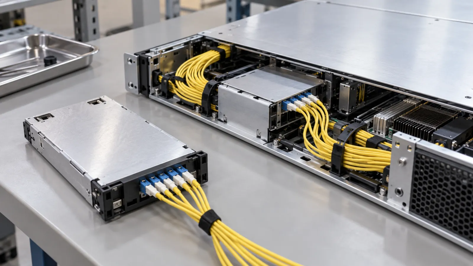
Summary: NPO and CPO fiber serviceability requirements should define what can be disconnected, inspected, replaced and retested without disturbing unrelated connections. The architecture label alone does not answer those questions. A useful request for quotation identifies the replaceable unit, the optical separation points, the technician’s access route and the acceptance evidence required after replacement.
On September 21, 2026, Adtran’s ECOC announcement describes discussions on AI interconnect architectures, including silicon photonics and co-packaged optics. This is a timely reason to examine maintenance requirements. The article below is procurement analysis, not a report of completed demonstrations or a claim that Liqiba supplies a particular optical engine.
Separate optical placement from service boundaries
Near-packaged optics and co-packaged optics describe approaches to placing optical functionality close to compute or switching electronics. They do not, by themselves, define an operator’s replacement procedure. Two systems using similar optical placement can expose different connectors, require different access tools and assign different components to the field-replaceable unit.
Marvell’s May 2026 Open CPX discussion describes work toward a defined socket and electrical connector framework for near- and co-packaged connectivity. That standardization effort is context for asking precise interface questions, not evidence that every proposed implementation already has interchangeable optical assemblies.
Start with a boundary drawing. Mark which items belong to the system vendor, which belong to the cabling supplier and which the operator may service. Include internal harnesses, external trunk connections, laser connections where applicable, strain relief and the supported separation sequence. Avoid making the passive-cabling purchase responsible for an undocumented internal optical interface.
Define the replaceable unit before counting connectors
Ask whether a failed component leads to replacement of an optical module, a harness, an entire board or a complete tray. Then identify every connection that must be opened to remove that unit. A connector being physically visible does not mean that field technicians are authorized to release it.
Require the vendor to distinguish a factory assembly interface from a service interface. A factory process may use alignment equipment, cleanliness controls or tooling unavailable in the data hall. Describing both interfaces as detachable can conceal a large operational difference.
A published Marvell CPO design example discusses detachable optical couplers and faceplate-connected laser modules in relation to serviceability. It illustrates the value of explicitly designed access points. Do not transfer that example’s construction, density or replacement assumptions to another supplier’s system.
Build a service-interface schedule
A short schedule should accompany the topology drawing. Give every planned service boundary a unique identifier and name the approved mating assembly. This makes a maintenance review much more concrete than asking whether the architecture is easy to repair.
| Schedule field | Question for the system owner | Required evidence |
|---|---|---|
| Replaceable unit | What is removed after this fault? | Approved removal and installation sequence |
| Optical boundary | Which connections are opened? | Interface and fiber mapping drawing |
| Access envelope | Can inspection tools and hands reach it? | Representative physical access review |
| Return to service | Which measurements and checks are repeated? | Acceptance checklist with recorded limits |
| Spare assembly | Which exact revision is compatible? | Controlled part number and substitution rules |
Keep optical compatibility and mechanical accessibility as separate columns. An assembly can mate correctly on a bench yet be impossible to disconnect safely after adjacent equipment is installed. Conversely, an accessible connector may still have the wrong fiber mapping or polish for the intended counterpart.
Calculate the connections disturbed by one replacement
Consider a deliberately hypothetical tray with eight removable harness groups. Each group terminates twelve duplex circuits. One group therefore carries 24 individual fiber paths, and all eight together carry 192. These figures describe this planning example only; they are not a specification for NPO, CPO or a commercial product.
If one harness group can be replaced independently, the minimum set requiring identification and reconnection is its twelve duplex circuits. If the mechanical access procedure instead requires opening all eight groups, 96 duplex circuits are disturbed. The difference matters even though the number of failed components is unchanged.
Translate that scope into a maintenance allowance
Assume the approved process takes an average of 45 seconds per duplex connection group for identification, authorized disconnection, reconnection and recording. Twelve groups require nine minutes; 96 groups require 72 minutes. These are connection-handling subtotals, excluding fault diagnosis, cleaning, optical tests, equipment shutdown and recovery.
The calculation is not an outage prediction and should not be used as a vendor performance claim. Its purpose is to expose a question for the pilot: how many healthy connections must be touched to replace one failed unit? Measure real task times during an authorized rehearsal rather than assigning a universal speed to technicians.
Check access in the installed configuration
Review the assembly with adjacent trays, cable managers, cooling connections and the intended rack position represented. Include the inspection probe, cleaning tool and any extraction tool. A drawing that shows connector pitch but omits the tool body can overstate practical accessibility.
Record whether a latch can be released without pulling the cable, whether the connector remains supported during inspection and where protective caps are kept. Assess the route in both operating and service positions. Drawer movement must not consume all available slack or tighten a bend behind a neighboring assembly.
Keep the maintenance loop separate from installation excess. The preterminated trunk length worksheet explains route-based length allowances. For an internal harness, replace its generic planning assumptions with the equipment vendor’s permitted motion, bend requirements and strain-relief locations.
Preserve mapping when assemblies look alike
A dense tray can contain visually similar harnesses with different lane assignments. Identify both ends and the intermediate service boundary. Document orientation, fiber positions and any conversion between parallel and duplex presentations before the unit enters production.
Specify how a replacement is checked against the installed configuration. Matching jacket color or connector family is insufficient. The maintenance record should identify the removed part, replacement revision, affected circuits and the verification performed before traffic returns.
Do not assume that a polarity correction permitted for a conventional patch cord is permitted inside the equipment. An internal assembly may have a controlled orientation or lane map that cannot be changed independently. Escalate undocumented substitutions to the system design owner.
Agree the post-replacement evidence
Separate physical inspection, passive optical testing and operational link checks. The system owner should define which boundaries are accessible for each measurement and what safe operating state is required. Not every internal interface can be connected to an ordinary field test instrument.
For accessible passive channels, retain the approved baseline and repeat the required measurements after disturbance. For internal optical engines, follow the vendor’s diagnostic and acceptance procedure. A restored link or a normal telemetry value can be useful evidence without proving every passive component meets its purchase specification.
The earlier ECOC fiber-design analysis covers broader channel and interoperability planning. This serviceability review adds a narrower requirement: demonstrate that the approved replacement process can preserve or re-establish that planned channel with traceable records.
Put realistic boundaries in the cabling RFQ
For an inquiry through the custom fiber optic cable assembly page, supply the controlled interface drawing, fiber mapping, route envelope, length endpoints, tolerance and required optical test method. State explicitly which interfaces are ordinary external cabling and which require approval from the system vendor.
Request confirmation of build scope before assuming availability. A supplier’s ability to make conventional patch cords does not establish capability to manufacture a proprietary optical-engine coupling assembly. Any specialized tooling, licenses or qualification requirements need their own documented confirmation.
Finally, attach the service schedule to the acceptance plan. Require a representative replacement rehearsal, record any healthy circuits that must be disturbed, and resolve incompatible revisions before deployment. The most useful serviceability claim is a reproducible procedure with clear boundaries, not a broad promise that a new architecture is inherently easy to maintain.
Frequently Asked Questions
Does NPO or CPO specify which part can be replaced in the field?
No. The system design and approved service procedure define the replaceable unit, accessible interfaces and permitted maintenance actions.
Are all detachable optical interfaces field-serviceable?
No. A factory assembly interface may require equipment or procedures unavailable to field technicians, even if it can be physically separated.
What should a fiber serviceability RFQ include?
Include the replaceable unit, separation points, controlled interface drawings, mapping, access envelope, spare revisions and post-replacement acceptance plan.
Does the worked handling time predict an outage?
No. It is a hypothetical connection-handling subtotal that excludes diagnosis, shutdown, cleaning, testing and recovery.
Can conventional patch-cord capability prove optical-engine assembly capability?
No. Proprietary interfaces, specialized tooling, licensing and qualification requirements need separate documented confirmation.







