
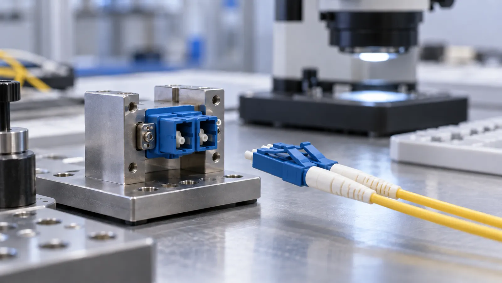
Summary: A fiber optic connector mating durability test evaluates repeated connection and disconnection under a defined method. A useful requirement states the device configuration, standard edition, cycle count, cleaning rules, optical measurements and mechanical acceptance criteria. A headline number of matings is incomplete without those conditions and should not be converted directly into years of field life.
This is a buyer’s specification and report-review guide. The example cycle schedule and calculations are hypothetical. They are not test results, a claim of Liqiba certification or a substitute for the licensed standard and the product’s applicable performance specification.
State exactly which interface is being exercised
A test can involve a connector pair held in an adapter, or a plug and equipment receptacle. Identify the complete arrangement, including the alignment component, ferrule construction, connector polish and fiber type. Testing a loose patch-cord connector against a reference counterpart does not automatically characterize every receptacle it may encounter in service.
The public description of IEC 61300-2-2:2026 identifies mating durability as a test of optical performance and mechanical degradation after repeated mating and unmating. Its revision summary includes plug-receptacle configurations, severity changes and revised cleaning criteria. Specify the edition explicitly rather than citing only the document number.
The public abstract does not supply a complete executable procedure. Obtain the applicable normative requirements through an authorized source and agree the product-specific severity before ordering a test. Do not infer an approved number of cycles or cleaning interval from this article.
Separate initial quality from durability
An initial insertion-loss result describes the connection under its initial measurement conditions. Durability asks how performance and physical condition change through repeated use. A good starting value is necessary for some acceptance plans, but it does not demonstrate a stable connector after many operations.
FOA’s connector testing explanation emphasizes that connection loss involves both connectors and their alignment arrangement. Its durability discussion combines repeated mating with loss measurements and inspection for wear or contamination. That is why the counterface and adapter identities belong in the report.
Keep the original low-loss patch-cord acceptance requirements separate from the durability clause. A report may satisfy one while omitting the other. Request both absolute optical results and the changes from baseline when the agreed specification requires them.
Make the cycle definition explicit
Define the starting condition, complete engagement, release and return to the starting condition according to the selected method. A supplier’s informal use of “operations” can count individual insertions or removals differently from a full mating cycle. Reconcile that terminology before comparing quotations.
Record the mechanism or manual fixture, alignment method, permitted speed and any required dwell. Excessive side loading or an improvised fixture can introduce stresses that do not represent the agreed test. Conversely, a fixture that bypasses a working latch may fail to exercise an important part of the assembly.
Identify whether the same counterpart remains with each specimen, and state when replacement is allowed. Substituting a fresh adapter during a sequence can change the result. If substitution is required by the method, retain the reason, component identity and cycle at which it occurred.
Specify cleaning as a controlled test condition
Cleaning is neither an undocumented rescue action nor something to prohibit universally. Use the selected standard’s rules and the approved test plan. Record permitted interventions, their timing and the relevant observations so that another reviewer can understand the sequence.
An optical reading after cleaning answers a different question from the preceding reading with contamination present. Keep both where the method requires them. Do not erase an unfavorable checkpoint or restart its cycle count without documenting the disposition.
For multi-fiber interfaces, use inspection equipment and criteria appropriate to that connector. The site’s MPO end-face inspection guide provides related inspection context. Inspection and optical measurements complement one another; a clean-looking end face does not establish its connection loss.
Create a checkpoint matrix before testing
The following is a planning template with deliberately assumed checkpoints. It is not the severity schedule from IEC 61300-2-2. Replace it with the approved schedule and identify the required measurement state at every point.
| Illustrative checkpoint | Optical record | Mechanical record | Intervention record |
|---|---|---|---|
| Baseline, before cycling | Specified wavelengths and reference setup | Housing, latch, ferrule and adapter condition | Initial preparation |
| 100, 200, 300 and 400 cycles | Required readings and change from baseline | Applicable visual or functional checks | Permitted cleaning or component changes |
| 500 cycles, final | Final values and acceptance decision | Final condition and functional acceptance | Complete deviation log |
A blank measurement is not a passing measurement. State how interrupted tests, damaged specimens and invalid instrument readings are handled. The report should distinguish a product failure from a test setup problem without silently excluding either from the specimen history.
Estimate the laboratory workload
Assume ten specimens, each assigned 500 complete cycles. That is 5,000 specimen-cycles. If one fixture processes one specimen at a time and an assumed cycle takes six seconds, pure cycling takes 30,000 seconds, or eight hours and twenty minutes. Setup, inspection and measurement pauses are additional.
With a baseline and five subsequent checkpoints, there are six measurement sets per specimen, or sixty sets across the ten specimens. If each set contains two wavelength conditions, that produces 120 specimen-wavelength records before accounting for additional fiber positions or repeat readings.
These counts expose resource requirements, not a required test speed or statistical sampling plan. Parallel fixtures may reduce elapsed time, but their capability and synchronized recording need validation. Sample quantity and acceptance sampling must come from the agreed quality plan.
Evaluate absolute loss and change separately
For arithmetic only, suppose a hypothetical connection starts at 0.20 dB insertion loss and later reads 0.28 dB under the same defined method. The increase is 0.08 dB. A limit on change and a limit on final absolute loss are different conditions; either, both or other criteria may apply.
Do not describe a small change as a pass unless the baseline, final value and measurement capability all satisfy the chosen rule. Changes close to measurement uncertainty deserve the specified treatment, not rounding chosen to obtain a favorable result.
A product-specific example is visible in Amphenol’s LC adapter information, which pairs a 500-cycle durability statement with a stated loss-change limit. Those values belong to that manufacturer’s listed product information. They are not a universal IEC limit or a specification for Liqiba products.
Do not convert a cycle rating into a lifetime warranty
Five hundred laboratory cycles do not establish a fixed number of years in a rack. Field contamination, handling, temperature, vibration and accidental loading differ from a controlled sequence. A mating-durability result is evidence about a defined stress, not proof against every failure mechanism.
Likewise, occasional service connections and repeatedly used test reference leads have different exposure patterns. A reference lead can require retirement based on its condition and verified performance even before an advertised cycle count is reached. Use the relevant maintenance and inspection procedure.
Ask for a traceable report, not a standalone badge
For a procurement inquiry through the fiber optic patch cord page, provide the connector interface, counterpart arrangement, intended use, selected standard edition and required evidence. Ask the supplier to confirm which tests are available and which require separate qualification.
The report should identify specimens, lots, fixtures, instruments, reference method, cycle sequence, interventions, readings and acceptance criteria. A statement that a connector is “durable” or “tested to IEC” without that scope cannot resolve a detailed engineering requirement.
Agree how design changes affect qualification. A different latch, ferrule, alignment sleeve or housing construction may change the relevant behavior even if the connector family name remains unchanged. A clear durability clause makes such substitutions visible before they become maintenance problems.
Frequently Asked Questions
Is a mating-cycle number a complete durability specification?
No. Define the interface arrangement, method and edition, cycle meaning, cleaning rules, measurement conditions and optical and mechanical acceptance criteria.
Does a 500-cycle rating mean a connector lasts a fixed number of years?
No. Laboratory mating cycles do not reproduce every field stress or establish a universal calendar lifetime.
Can the adapter be ignored during a connector durability test?
No. The counterpart and alignment arrangement can affect connection performance, so their identities and permitted changes belong in the test record.
Should cleaning always be prohibited during cycling?
No. Follow the selected standard and approved plan, and document permitted cleaning and other interventions without hiding earlier observations.
Is loss change the same as final absolute insertion loss?
No. A change is calculated relative to the baseline; the final absolute value is a separate result. Apply every criterion required by the specification.







