
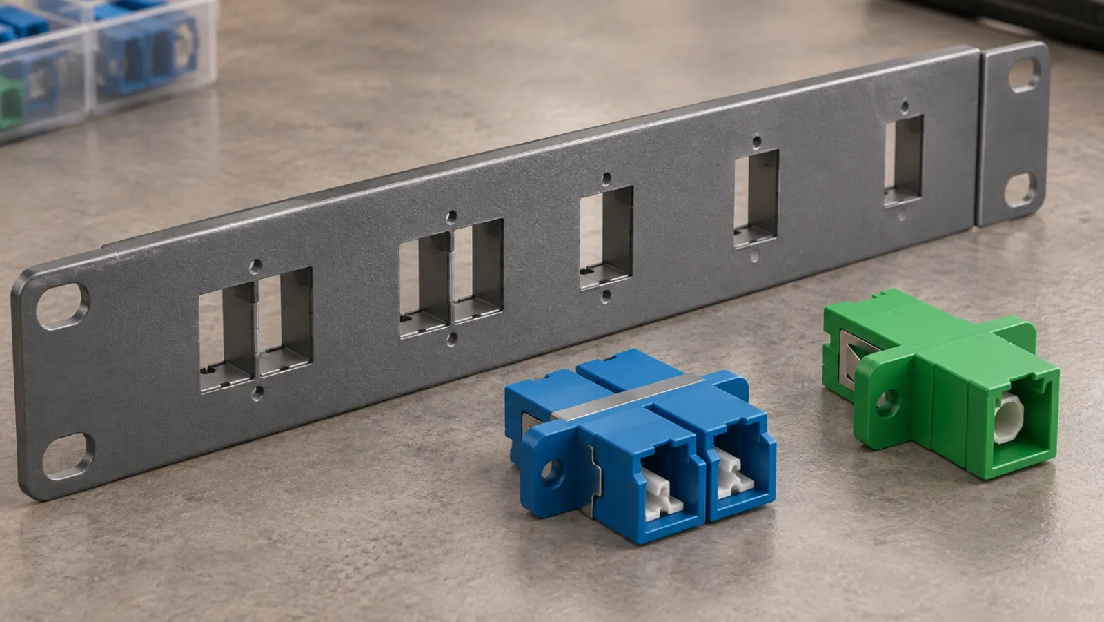
Summary: Fiber optic adapter panel cutout dimensions must come from the controlled drawing for the exact adapter variant. Connector family, port count and housing color are not enough. Check the opening, mounting method, panel thickness, tolerances, flange clearance and rear routing space before ordering a panel or approving a substitute adapter.
This guide is a mechanical selection worksheet, not a universal LC or SC drilling template. Every numerical fit example below is hypothetical. Do not fabricate an opening from these example dimensions or from a photograph of a connector.
Distinguish three different interfaces
The optical connector mates with the adapter at one interface. The adapter attaches to the panel at another. The cable boot and routing system occupy a third envelope behind the panel. Compatibility at one interface does not establish compatibility at the other two.
The LC versus SC connector guide addresses optical connector selection. Panel design needs additional information: the precise adapter housing variant, attachment features and the approved opening. Avoid treating the connector’s general dimensions as the adapter’s panel-cutout dimensions.
A catalog’s overall width can include a flange that remains outside the opening. Likewise, a clip can flex during insertion and engage a thickness range not evident in a front view. Identify which drawing dimension describes which feature before sending dimensions to a fabricator.
Treat a shared footprint as a starting point
Some products intentionally reuse established panel openings. For example, SENKO’s SN SC-footprint adapter description identifies variants intended for legacy SC-simplex/LC-duplex and SC-duplex/LC-quad cutouts. That is a product-specific compatibility statement, not evidence that all adapters with similar names interchange.
A retrofit can preserve the opening while changing the optical connector, channel count, latch access or rear cable arrangement. Record those consequences explicitly. A part that snaps into an old panel can still require a new harness, a different inspection tip and a revised port map.
Ask the proposed supplier to identify its supported footprint and provide a revision-controlled drawing. If the proposed substitute is only described as “SC type,” request clarification rather than assuming that one familiar rectangle is sufficient.
Collect the complete mounting information
Record the opening width and height, corner geometry, hole spacing where used, panel thickness range and permitted attachment method. Include the viewing direction and datum references. Dimensions without a clear reference face can reverse the apparent position of asymmetric features.
Amphenol’s LC adapter range lists multiple flange types, shutter arrangements and mounting clips. This illustrates why a connector family does not define one mechanical part. Select the actual orderable variant before confirming the metalwork.
| Drawing item | What to verify | Common procurement omission |
|---|---|---|
| Cutout | Finished opening and tolerance | Using the outside flange width instead |
| Retention | Clip or screw arrangement | Ordering a different flange variant |
| Thickness | Supported finished panel thickness | Ignoring coating or reinforcement |
| Clearance | Adjacent flanges, latches and tools | Checking only the empty panel |
| Rear envelope | Adapter depth, boot and fiber routing | Closing the enclosure onto a cable bend |
Do not add a generic clearance value to every manufacturer’s cutout. The recommended opening may already include a fit allowance. If additional clearance is proposed for manufacturing reasons, obtain approval rather than modifying the opening until a sample happens to fit.
Use worst-case dimensions for an initial fit screen
Assume a hypothetical finished opening has width 13.30 ±0.10 mm. Its minimum width is 13.20 mm. Suppose a hypothetical adapter feature that passes through the opening is 13.00 ±0.10 mm wide, so its maximum width is 13.10 mm. The smallest total width clearance is therefore 0.10 mm.
This total clearance is not 0.10 mm on each side. In an ideally centered arrangement, it corresponds to 0.05 mm per side, but actual positioning and retention can make the gaps unequal. Repeat the screening in the other relevant dimensions and account for corner geometry.
Determine whether coating is already included
If the opening dimension instead describes unfinished metal, an assumed 0.04 mm coating on each opposing edge reduces the width by 0.08 mm. The previous minimum opening would become 13.12 mm, leaving only 0.02 mm against the assumed maximum adapter feature. This is a sensitivity example, not a fabrication tolerance recommendation.
Do not subtract coating twice when the drawing already specifies the finished opening. Clarify whether the dimension applies before or after finishing, and consider burrs and local coating buildup through the approved manufacturing process. A positive arithmetic clearance does not establish clip engagement or a mechanically acceptable fit.
Check thickness and retention separately
A spring clip or molded latch must engage the panel as designed. An opening can be wide enough while the panel is too thick for full engagement. A panel that is too thin may leave an assembly insufficiently retained, depending on the design.
Include the finished thickness, coating, local reinforcement and any gasket or bracket that lies in the retention path. Do not treat these layers as interchangeable simply because their summed thickness appears acceptable. The drawing may rely on a particular surface shape or attachment sequence.
For screw-mounted variants, verify hole location, fastener requirements and flange support. Tightening force and hardware selection should follow the approved instructions. Do not use a screw to force a mismatched housing into an undersized cutout.
Count adapter positions, fiber paths and circuits
Panel descriptions sometimes use “port” to mean an adapter housing, an individual optical position or a duplex circuit. State the convention in the bill of materials. This prevents a panel order that meets the advertised port count but supports only half the required circuits.
For an illustrative design, assume each LC-duplex adapter provides two independent fiber positions and serves one conventional two-fiber duplex circuit. Ninety-six such circuits require 96 adapter positions and 192 fiber paths. A panel with 24 of those adapter positions would require four panels for the active circuits.
This calculation does not approve the enclosure’s physical or optical capacity. Reserve positions, splice storage, bend requirements and cable entry space still need review. It also does not apply unchanged to single-fiber bidirectional service or another connector architecture.
Review rear space with the real assembly
Place the intended connector boot, pigtail or patch cord behind the adapter in the layout. Check the route with covers and drawers closed, not just in an open assembly photo. A deeper shuttered adapter or different boot can change the usable space even when the front opening remains the same.
The 250 versus 900 micron pigtail selection guide provides the related routing review. Buffer construction and stored length can influence the rear arrangement, but neither replaces a check of the actual connector-to-tray path.
Include access for connector release, inspection and cleaning at the expected installed density. A panel can pass a static fit check while making routine servicing impractical. Use a representative populated sample when a drawing alone cannot resolve tool access or cable movement.
Make sample approval repeatable
Identify the panel drawing revision and adapter part number on the sample record. Check insertion, full retention, intended removal and clearance using the approved procedure. Record any interference or incomplete seating before the rest of the panels are fabricated.
Do not alter the sample with unrecorded filing and then call the original drawing approved. If a controlled change is necessary, revise the drawing and repeat the relevant check. Preserve the distinction between an approved production fit and a one-off workshop adjustment.
Write a drawing-led purchase request
For an inquiry through the fiber optic adapters page, provide the connector interface, required fiber positions, mounting variant, panel drawing, finished thickness and rear-space constraints. Request confirmation of the exact adapter drawing and any proposed substitutions before placing the production order.
Optical requirements still belong in the specification: fiber compatibility, connector polish, applicable loss criteria and test evidence. A mechanical sample does not establish optical performance, and a low-loss test result does not establish panel fit.
The final acceptance package should tie the adapter variant to a controlled panel revision and representative assembly check. That simple discipline makes shared footprints useful without turning them into an unsupported promise of universal interchangeability.
Frequently Asked Questions
Is there one universal panel cutout for every LC adapter?
No. Use the controlled drawing for the exact adapter variant, including its retention method and supported panel thickness.
Does an SC footprint guarantee optical compatibility?
No. A shared mechanical footprint does not establish connector interface, fiber mapping, polish or optical performance compatibility.
Should coating always be subtracted from the opening dimension?
Only when the specified dimension is for unfinished metal. Do not subtract coating again if the drawing already defines the finished opening.
Does positive calculated clearance prove that an adapter fits?
No. Check the other dimensions, corners, retention, thickness and access envelope, and perform the approved representative assembly check.
How many fiber positions does a conventional LC-duplex adapter provide?
It provides two individual fiber positions. State whether the panel port count means adapter positions, individual fibers or duplex circuits.







