
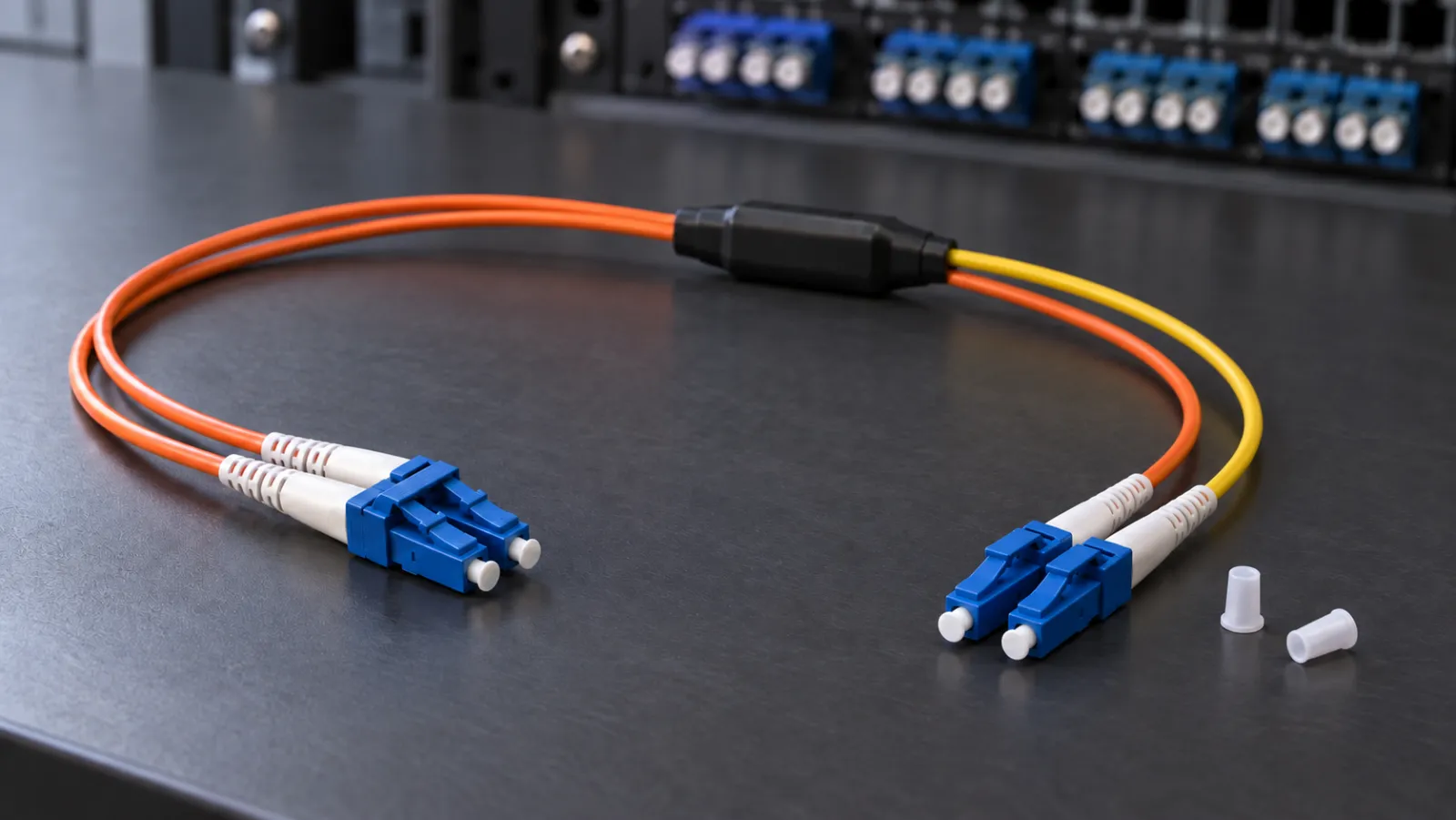
Summary: A mode conditioning patch cord for 1000BASE-LX is a specialized launch assembly, not a universal adapter between single-mode and multimode networks. Identify the exact optical module and installed fiber first, then verify the manufacturer-required cord, transmit orientation, channel length and acceptance procedure. The worksheet below separates those decisions so a physically mating connector does not become an unsupported network design.
Start with the installed link, not the connector color
Legacy campus links often survive several generations of switches. A purchase request may say only “LC duplex, 1 Gbit/s,” while the installed cable contains 62.5-micron fiber, intermediate SC panels and undocumented patching. Those missing details determine whether a proposed replacement is appropriate. Connector shape tells you how a plug mates; it does not identify the complete optical application or prove the fiber bandwidth.
Build a link record with endpoint names, equipment models, optical-module part numbers, software support, fiber classification, measured or documented channel length and every intermediate connection. Separate facts confirmed by records from assumptions awaiting inspection. For classification background, use the OM3, OM4 and OM5 comparison, but obtain the actual installed cable identification before ordering. A jacket color is a useful clue, not sufficient evidence.
Understand what mode conditioning changes
An offset-launch assembly controls how light enters a multimode core. It does not convert the whole installed channel into single-mode fiber, add Ethernet protocol conversion or remove bandwidth limits. Cisco’s mode-conditioning application bulletin specifies conditioning for the listed 1000BASE-LX/LH applications over FDDI-grade, OM1 and OM2 fiber. It excludes 1000BASE-SX and says not to use the assembly on OM3 in those applications. Treat these as documented application rules, not permission to combine arbitrary modules and fibers.
Juniper’s SFP-1G-LX-C specifications likewise identify offset-launch conditioning for multimode operation and require the conditioner fiber size to match the installed 50- or 62.5-micron fiber. This is a useful second check on procurement vocabulary. A cord described simply as “single-mode to multimode” omits the controlled launch arrangement and may not be the required product.
Keep transmission direction explicit
The conditioning junction belongs in the transmit path prescribed by the assembly and equipment documentation. A duplex connector can hide the distinction between its two legs. Require a drawing that identifies the equipment end, cable-plant end and transmit leg without depending solely on jacket colors. Review both endpoints independently: the transmitting port at the far end is a separate launch, even though it serves the same duplex circuit.
Use a compatibility decision table
| Question | Required evidence | Action if unresolved |
|---|---|---|
| Which optical application is supported? | Exact module and platform documentation | Hold module and cord selection |
| What fiber is actually installed? | Cable record, identification and verified route | Survey the channel before ordering |
| Is conditioning required or prohibited? | Application-specific manufacturer instruction | Seek written clarification |
| Which core size and orientation apply? | Assembly drawing matched to the channel | Reject an ambiguous generic description |
| Does the complete channel meet limits? | Length, loss and applicable bandwidth evidence | Evaluate a different supported solution |
Record the revision and date of the document used for each decision. An archived bulletin can explain a legacy deployment, but the replacement module may have different conditions. When two documents appear inconsistent, do not choose the more convenient instruction. Ask the equipment supplier which document governs the exact part number and operating combination, then retain that response with the design record.
Calculate the channel and the purchase quantity separately
Consider a hypothetical refurbishment of eight duplex links. Assume the approved equipment instructions require one duplex conditioning assembly at each endpoint. The installed quantity is eight links multiplied by two endpoints, or 16 assemblies. If the project separately chooses two spare assemblies, the order becomes 18. That spare allowance is an inventory decision, not an optical-standard requirement. Specify whether a quoted “pair” means two connectors, one duplex cord or two complete endpoint assemblies.
For one example channel, assume 410 m of installed fiber, two 3 m endpoint assemblies and 14 m of intermediate jumpers. The total path length is 410 + 6 + 14 = 430 m. If the exact approved application has a documented 550 m channel limit under its stated fiber conditions, the arithmetic leaves 120 m below that length limit. This is a conditional example, not a universal reach claim or a recommendation to spend all remaining length allowance.
Length alone does not approve the link. The complete channel must also satisfy the relevant optical loss, launch, receiver and fiber-bandwidth requirements. Do not subtract a length margin from a loss margin or treat them as interchangeable. If any intermediate cable type is unknown, a neat total in the spreadsheet does not resolve that uncertainty. Flag the affected segment and close the identification gap before release.
Write an RFQ that a supplier can answer precisely
Include the supported application, multimode core size, connectors at each end, polish, duplex orientation, individual leg lengths, overall assembly length and environmental requirements. Ask for the manufacturer’s assembly drawing and identification scheme. Define the delivered length tolerance and whether protective junction sleeves must fit through existing managers. A cord that is optically appropriate but cannot be routed without an excessive bend is still unsuitable.
For a fiber patch-cord and assembly inquiry, attach the equipment requirement and request written confirmation of the proposed construction. Do not interpret the availability of ordinary patch cords as proof that a particular offset-launch assembly has been qualified. Ask the supplier to distinguish its standard product, a proposed custom design and any option it cannot support. That distinction prevents a quotation from silently becoming a compatibility guarantee.
Make substitution review practical
List the attributes that may change without a new optical review, such as an approved packaging option, and those that require one, such as core size, junction construction, polarity or part-number revision. Keep a photograph of the actual assembly identification in the private project record when available. The illustrative image accompanying this article is not a dimensional drawing or evidence of a supplied product.
Plan installation and acceptance before the outage
Schedule an authorized maintenance window and verify service isolation before handling fibers. Never look into an optical port. Prepare the agreed cleaning and inspection tools, then follow the inspect, clean and reinspect procedure for connector handling. Keep dust protection on unused interfaces and avoid pulling on the conditioning junction. Installation should follow the exact assembly instructions, including transmitter identification at both ends.
Document the pre-change configuration so it can be restored if the approved acceptance tests fail. Record the installed assembly identifiers, route and endpoint orientation after the change. Acceptance should cover the project-required optical checks and supported traffic tests, including relevant interface error counters over an agreed observation period. A link light proves only that some communication condition has been established; it is not a substitute for the planned evidence.
If received power is outside the module’s allowed range, stop and investigate using the manufacturer’s procedure. Do not add an arbitrary attenuator as a substitute for resolving incorrect fiber, launch arrangement or equipment selection. Optical power and modal behavior are separate issues. The troubleshooting record should explain which requirement failed and which change corrected it, rather than documenting only the final green indicator.
Preserve a useful maintenance baseline
Store the final link record alongside the equipment inventory and patching schedule. Mark spare assemblies by approved application and fiber size so they are not mixed with ordinary jumpers. At future switch replacement, reopen the compatibility decision rather than copying the previous cord order automatically. The best outcome is a documented, supportable legacy link with a clear migration path, not a special cable whose purpose disappears when the original installer leaves.
Frequently Asked Questions
Is a mode-conditioning cord a universal single-mode to multimode converter?
No. It is a specialized launch assembly for supported optical applications. It does not convert Ethernet protocols or make arbitrary transceivers and fiber types compatible.
Should every 1000BASE-LX link use a conditioning cord?
No. Check the exact module, platform and installed fiber against the manufacturer instructions. Requirements differ between supported fiber applications.
Can I choose the cord using connector color alone?
No. Verify the installed fiber classification, core size, equipment application and assembly drawing. Connector and jacket colors alone do not establish compatibility.
How many assemblies does the eight-link example require?
Under its explicit assumption of one duplex assembly at each endpoint, eight links require sixteen installed assemblies, plus any separately chosen spares.
Does a link light or passing length check prove acceptance?
No. Complete the approved optical and traffic tests and confirm the applicable loss, launch, receiver and fiber-bandwidth requirements.







